
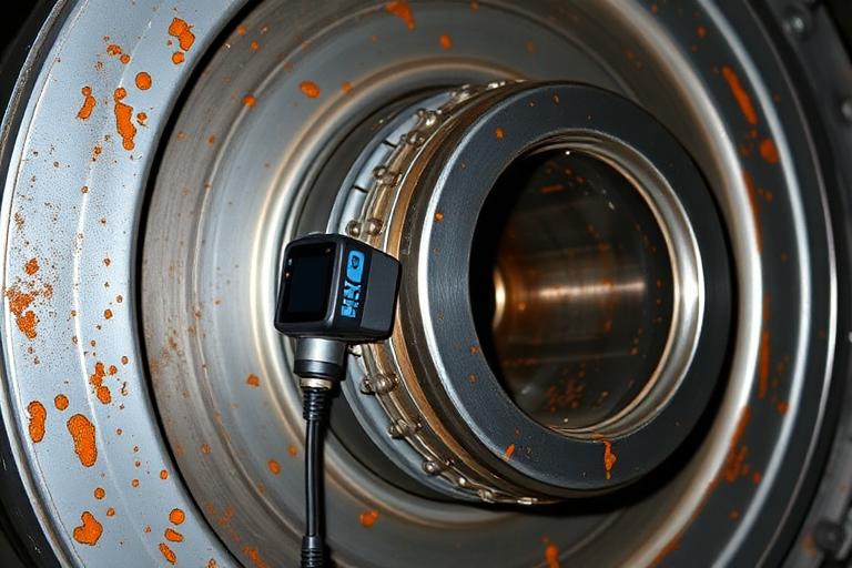
A utility scale steam turbine generator train develops significant vibration. Inspection confirms loose internal generator components. The temptation at that moment is to close the investigation, tighten what is loose and return the unit to service. That decision restores the machine. It does not establish why the condition developed, whether it will develop again, and whether the same latent condition exists in sister units.
01
One machine train, three diagnostic systems
A steam turbine, reduction gearing and a synchronous generator are mechanically coupled, so energy can move between them. That establishes a transmission path. It does not establish a causal direction. The argument that the generator was vibrating and the turbine is connected through the gearbox, therefore the turbine must be the source, is an assumption wearing the clothes of an explanation.
Each subsystem is diagnosed on its own evidence first. Only after the generator, gearbox and turbine hypotheses have been independently tested does the investigation ask whether shaft orders, phase relationships, load dependence, transient behavior and structural response support an interaction among them.
This is the point at which multidisciplinary work stops being a marketing phrase. A vibration analyst can describe the signal. A generator specialist can identify internal looseness. A gearbox engineer can read mesh behavior. A turbine engineer can assess rotor dynamics. The owner still needs one party accountable for integrating that evidence into a single defensible conclusion.
The loose component may explain how the machine was moving. It does not necessarily explain why the component became loose.
02
What the measured vibration establishes and what it does not
Amplitude states that something changed. Frequency narrows the candidate mechanisms. Neither selects one. Synchronous energy is consistent with unbalance, and equally consistent with a bowed rotor, a shifted coupling, thermal growth or a degraded support. The discrimination comes from the measurements taken around the signal rather than from the signal alone.
Load dependence is frequently offered as proof of electromagnetic origin. It is not. Thermal growth, alignment change under load, bearing eccentricity and steam force all vary with load. Load dependence narrows the field. It does not close it.
- Phase, both absolute and relative between measurement planes
- Orbit shape and precession direction at journal bearings
- Shaft centreline position from cold turning gear through full load
- Order tracked run up and run down behavior, and the speed at which response peaks
- Whether the change was gradual, step wise, or coincident with a specific operating event
- Behavior at the same speed under different load, excitation and temperature conditions
03
The generator: electromagnetic forcing and structural response
A synchronous generator is excited at twice electrical frequency by the magnetic forces acting between the core, the stator bars and the end winding structure. On a 60 Hz system that forcing sits at 120 Hz. The forcing is always present. Whether it produces meaningful motion depends on how close a structural natural frequency of the affected assembly sits to that forcing frequency, and on how stiff the restraint system remains under operating temperature and load.
That distinction matters in an investigation. Twice electrical frequency is not a fingerprint of end winding looseness. It is the excitation. Significant response at that frequency is evidence that something in the supported structure has moved toward resonance, which is why impact and bump testing during an outage, together with experimental modal analysis, is the measurement that converts a suspicion into a finding.
The most discriminating test available on this class of machine is a run down with the field tripped. Forcing that disappears with excitation is electromagnetic. Response that persists as the machine coasts is mechanical. Very few other measurements separate the two causes as cleanly, and the opportunity to take it usually exists only once.
Rotor side mechanisms are evaluated in parallel: mass unbalance, thermal sensitivity of the rotor with field current, inter turn shorts indicated by a flux probe together with load dependent change in synchronous response, shaft voltage and current activity, bearing and pedestal condition, and cooling system behavior. Partial discharge measurement is an insulation condition test, not a vibration diagnostic. It becomes relevant when movement is suspected of having abraded insulation, and it is interpreted in that context.
04
Critical internal generator components and what each one fails from
The internal condition of the machine is anonymized here. The discipline is not. An investigation of this type examines each restraint, support, fit and fastening system in the machine, records its as found condition, and asks what dynamic behavior that condition would be expected to produce.
- End winding support
- Blocking, ties, lashing, bracing rings and conformable packing. Loss of restraint lowers assembly stiffness, moves natural frequencies and allows relative motion between bars. Dusting, fretting powder, glazed contact faces and migrated packing are the physical record of that motion.
- Slot portion and wedging
- Wedge tightness, ripple springs and side packing. Bar movement in the slot abrades groundwall insulation and greases the slot. Wedge tap survey and mapped tightness across the core length establish extent rather than a single observation.
- Core and frame
- Lamination tightness, keybars, through bolts and frame to foundation supports. Core looseness and support degradation change the path through which force reaches the foundation, and can produce frame and foot response that is mistaken for a rotor problem.
- Connection and lead supports
- Circuit rings, series and phase connections, terminal leads and their brackets. These assemblies carry high current and have their own natural frequencies, and their supports are a recurring site of restraint loss.
- Fastening and preload systems
- Bolted joints, locking devices, torque and preload condition. A joint that has relaxed behaves differently from a joint that was never correctly preloaded, and the as found evidence usually distinguishes them.
- Fits and interference
- Shrink fits, spigots, dowels and machined interfaces where the design intent is a rigid connection. Loss of interference is a stiffness change before it is ever a visible defect.
- Bearings, seals and cooling components
- Bearing clearance and alignment, oil and seal condition, coolers, baffles and ducting. These affect both the response of the machine and the temperature field acting on everything above.
05
The gearbox as an independent subsystem
The reduction gearing is not a passive connector. It is a dynamic system with its own excitation, its own bearings and its own failure modes, and it is tested on its own evidence before any statement is made about transmission between turbine and generator.
Torsional behavior deserves specific attention in a geared train and is the item most often absent from vibration reports. Torsional natural frequencies can sit close to mesh excitation or to electrical excitation, and torsional response is largely invisible to the lateral measurements that make up routine monitoring.
- High speed and low speed shaft response, with X and Y proximity probes and a phase reference on each shaft
- Gear mesh frequency, its harmonics and the sideband structure around it
- Journal bearing behavior, clearance, lift check, shaft position and axial movement
- Casing response in horizontal, vertical and axial directions
- Tooth contact pattern and transmission error assessed under load, not only on a static blue check
- Lubrication condition, oil temperature and pressure, debris and ferrography
- Alignment as found and hot, soft foot, thermal growth of pedestals, coupling condition and lock up in gear type couplings
06
The turbine as an independent subsystem
Turbine mechanisms are tested on the same terms. Rotor unbalance, thermal bow, eccentricity at turning gear, differential expansion and casing distortion, rub evidence in orbit shape, oil film stability including whirl and whip, steam whirl at high load, bearing and pedestal condition, foundation and grout condition, and alignment as found against the hot condition the machine actually runs in.
Startup, shutdown and load change behavior carry more diagnostic weight than steady state data. A mechanism that only expresses itself through a speed range or a thermal transient is frequently invisible in the trend that triggered the investigation.
07
Correlation only where the evidence supports it
Interaction between subsystems is a finding that must be earned. It requires measured correspondence in shaft order, phase, amplitude change against load and temperature, electrical condition and synchronized time. Proximity is not correlation, and correlation is not causation.
Where the evidence supports interaction, it is stated as interaction. Where it does not, the report says that the available evidence does not establish transmission between subsystems, and identifies what additional measurement would resolve it.
08
Instrumentation and analysis: who owns it and what tier it belongs to
Not every measurement in this list belongs in every investigation. Standard monitoring is what the plant already has. Outage inspection is what becomes available when the machine is open. Specialist testing is hypothesis driven, is selected because a specific mechanism needs to be proved or excluded, and requires owner and OEM concurrence before it is performed.
- Standard monitoring
- X and Y proximity probes and phase reference on turbine, gearbox and generator bearings, casing and pedestal accelerometers, axial and thrust position, eccentricity, differential expansion, bearing metal and oil temperatures, speed, generator winding temperatures, permanent condition monitoring through Bently Nevada System 1 and portable analyzers for route data.
- High resolution acquisition
- ADRE class dynamic acquisition for transient capture, with spectra, waveform, orbit, phase, shaft centreline, order tracking, cascade and waterfall plots, gear mesh and sideband analysis and load state based trending.
- Generator specialist testing
- Fibre optic end winding accelerometers and online end winding vibration monitoring, impact and bump testing, experimental modal analysis, rotor flux probe, shaft voltage and current monitoring, partial discharge with capacitive couplers, insulation resistance and polarization index, winding resistance, and core testing such as EL CID or a core loop test where the failure hypothesis requires it.
- Outage inspection
- Borescope and internal inspection, wedge tap survey and mapped wedge tightness, blocking and tie condition, dusting and fretting evidence, gear tooth and contact pattern inspection, bearing condition, alignment records and as found dimensional capture.
- Engineering modelling
- Rotordynamic modelling in DyRoBeS or XLRotor where a rotor or bearing hypothesis needs a model, operating deflection shape in ME'scope, modal and harmonic analysis in ANSYS Mechanical for a structural or support hypothesis, and gearbox tooth contact or structural modelling in KISSsoft or Romax where a specific gear hypothesis warrants it.
09
Operating and electrical data the machine record must be read against
Vibration data alone will not resolve a case of this type. The dynamic record is read against real load, excitation, thermal and event history, taken from the historian rather than from recollection.
Time synchronization across machinery monitoring, the DCS or historian and the electrical and protection records is an evidence quality issue in its own right. Clocks that differ by seconds will invert a sequence, and a sequence that is inverted will support the wrong conclusion with apparent confidence.
- MW, MVAR, power factor, terminal voltage and current, and negative sequence current
- Field and excitation condition, and behavior through excitation changes
- Shaft speed, steam conditions and unit operating state, including partial load and transient periods
- Bearing, oil and generator temperatures, and lubrication system pressures
- Alarm, trip and event history, and prior balancing, alignment and outage work
- Previous internal inspection findings and any repeat of the same finding on sister units
10
From physical finding to root cause: the fabrication and installation question
Finding a defect is not the same as proving the cause. A loose internal component may be the immediate mechanical condition associated with the vibration, and still be an effect of something introduced long before the machine entered service. The investigation therefore carries the causal chain further than the physical finding.
Where records permit, the investigation examines whether the required quality controls were performed, documented and independently verified during fabrication and field installation. Missing documentation does not by itself prove improper installation. The conclusion depends on whether physical evidence, records and operating behavior collectively support the hypothesis, and where records are incomplete the report says so rather than converting an unverified concern into a finding.
- OEM fabrication and assembly procedures, and installation specifications
- Inspection and test plans, with hold points and witness points and evidence they were attended
- Torque, preload and fastening verification records
- Fit up, dimensional and alignment records, and restraint or support verification
- Factory and field acceptance documentation, and as built verification
- Nonconformance reports, punch list items and their closeout evidence
- Commissioning records, inspection sign offs, OEM field service reports and turnover documentation
- Observed condition
- Elevated vibration on the machine train, characterized by frequency, phase, load dependence and transient behavior.
- Physical finding
- Loose internal generator components confirmed by inspection, with location, extent and as found condition documented before anything is disturbed.
- Failure mechanism
- Loss of stiffness or restraint, relative movement, resonance proximity, or another mechanism supported by measured response rather than inferred from the defect.
- Potential root cause
- A fabrication, assembly, installation or commissioning condition that was not adequately controlled or verified before the equipment entered service.
- Systemic cause
- Weakness in quality control, inspection, acceptance or commissioning governance, stated only where the evidence supports it.
11
The investigation sequence
The order matters, because several categories of evidence are perishable and several conclusions are only defensible if the work that preceded them was done in the right sequence.
- 01 Define the exact machine train from nameplates and OEM drawings: turbine sections, shaft speeds, gear ratio, generator speed, bearings, couplings, sensor locations, electrical frequency and ratings
- 02 Preserve the evidence: monitoring data, trip and alarm records, vibration history, historian data, maintenance and inspection records, photographs, alignment records and prior outage reports, before records roll over or condition is changed
- 03 Synchronize the evidence to a common time reference across machinery monitoring, historian and electrical systems
- 04 Build competing hypotheses and keep the generator, gearbox and turbine sets separate
- 05 Characterize the vibration across amplitude, frequency, phase, waveform, orbit, shaft centreline, order, load dependence and transient behavior
- 06 Investigate the generator internally, and determine whether the location and condition of the loose components correspond with the measured dynamic behavior
- 07 Investigate the gearbox independently, testing shaft, mesh, sideband, bearing, alignment, contact and lubrication hypotheses
- 08 Investigate the turbine independently, testing rotor, bearing, alignment, thermal and structural mechanisms
- 09 Correlate only where measured evidence supports correlation
- 10 Rank the hypotheses, stating for each the supporting evidence, the inconsistent evidence, the additional evidence required and the confidence level
- 11 Examine fabrication, installation and commissioning records where the physical evidence raises a latent defect hypothesis
- 12 Correct the supported mechanism, and explain why the repair addresses the causal mechanism rather than suppressing the measured symptom
- 13 Validate against pre and post intervention vibration, operating behavior and inspection evidence, then submit the conclusions to Responsible Engineer review by an engineer outside the primary discipline
12
Why this matters beyond one machine
A vibration repair restores the machine. A root cause investigation establishes whether the same latent fabrication or installation risk exists elsewhere in the fleet. Those are different deliverables and they carry different value.
If the initiating condition was introduced during fabrication or installation, the true corrective action is not simply tightening or repairing the affected component. It is strengthening the quality controls that allowed the condition to enter service.
That is the path from failure investigation to fabrication and installation records review, to field quality surveillance, to commissioning assurance, and finally to prevention of recurrence on the next unit rather than explanation of the last one.
13
Consequence and exposure
The engineering question is inseparable from the commercial one. A machine of this class does not fail quietly, and the decisions that follow are made by people who need the causation question answered in terms they can act on.
- Outage and replacement power
- Forced outage duration on a base load unit, and the cost of replacement energy or contractual unavailability for the period the machine is out.
- Repair scope and lead time
- Generator rewedge, rewind or core work, and gearbox or rotor repair, each with long lead times that dominate the return to service schedule.
- Insurance causation
- Whether the loss arises from a covered event, from wear, or from a defective workmanship or design condition, which determines the coverage position and the evidence the adjuster requires.
- Warranty and responsibility
- Whether the condition falls within an OEM or installer responsibility window, and whether the records support that position.
- Restart risk
- Whether the machine can be returned to service safely before the mechanism is understood, and under what monitoring and operating restrictions.
- Fleet recurrence
- Whether the same fabrication, installation or commissioning condition is present on sister units, which converts a single repair into a fleet inspection decision.
Related Capability
Continue Reading
- It's Not Just a Gasket: Eliminating Flange Leaks Through Bolted Joint Engineering, Controlled Bolting, and Assembly Governance
Pressure Systems
- Spring Hangers: Selection, Setting, Inspection and the Failures They Prevent
Machinery Diagnostics
- Criticality Is Not Priority: How Engineering Leaders Decide What Work Comes First
Asset Advisory