
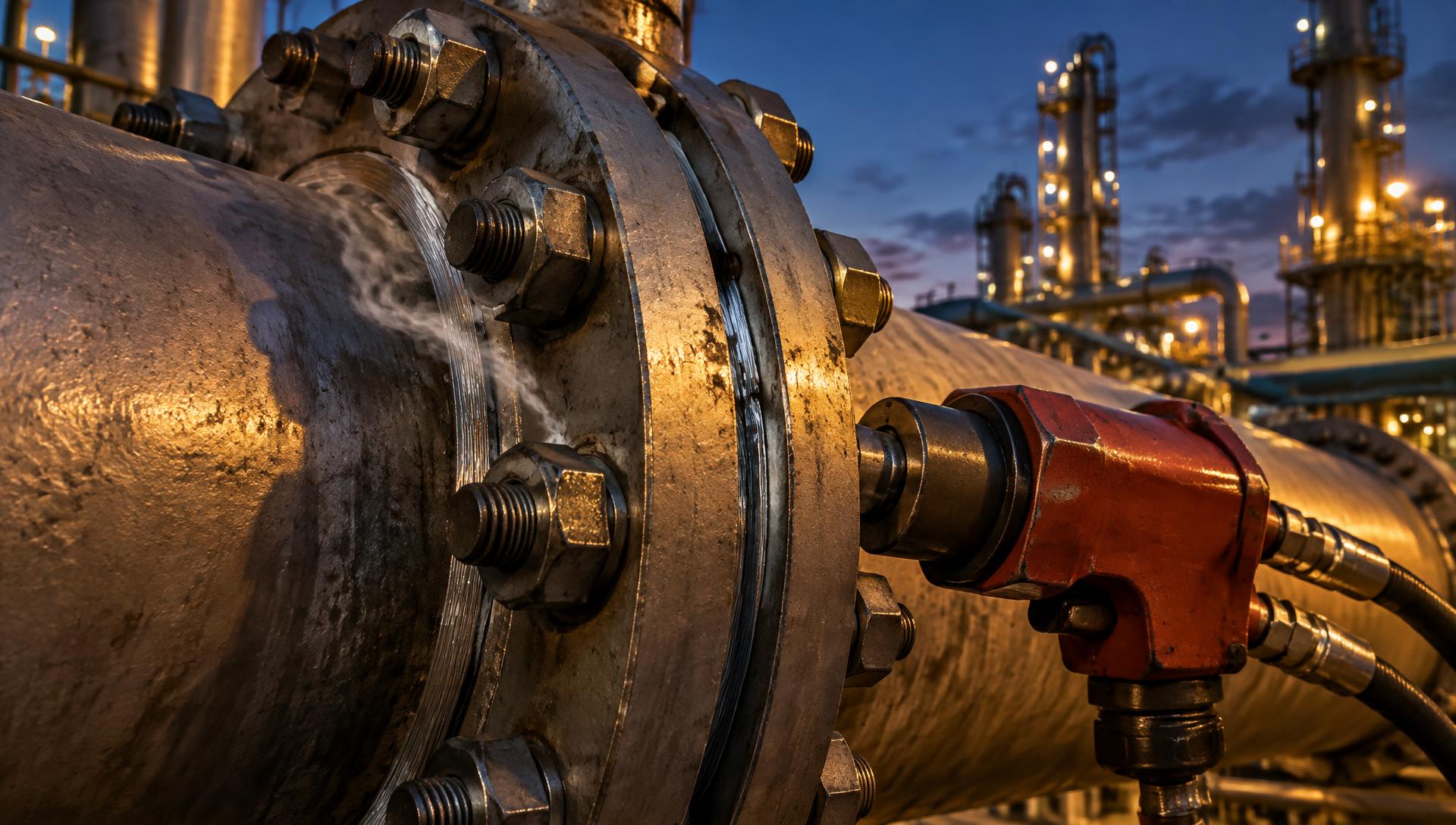
When a flange leaks, the work order usually says the gasket failed. Often it did not. The gasket was the wrong construction for the chemistry, the flange face carried a radial scratch, the studs were tightened with an unknown nut factor, the piping was pulled into alignment with the bolts, or preload was lost on cooldown. A gasket does not seal by existing between two flanges. It seals because the joint is engineered to generate and maintain sufficient compressive stress across the gasket throughout the operating envelope. This article sets out how BlackOut Power Group approaches bolted flange joints from specification to turnaround, and how an owner can manage thousands of them as governed, traceable assets.
01
The bolted flange joint is a spring system, not a sandwich
A bolted joint is an equilibrium between elastic members. The studs are stretched in tension. That stretch clamps the flanges, which rotate slightly as beams, and compresses the gasket, which behaves as a compressible sealing element with limited recovery. Every operating event changes that balance.
Pressure adds end thrust that unloads the gasket. Heat-up grows the flanges and bolts at different rates. Cooldown can shed preload faster than the gasket can recover. Creep and relaxation slowly remove stretch from studs and thickness from the gasket. A joint that was tight at assembly can be marginal at temperature and leaking eight hours after a trip.
- Assembly: the gasket must reach seating stress and conform to the flange surface.
- Pressurization: residual gasket stress after end thrust must stay above the operating sealing requirement.
- Heat-up: differential expansion between stud and flange material can crush or unload the gasket.
- Cooldown and trips: thin flange rims cool faster than insulated studs and preload can be lost.
- Long term: creep, relaxation and vibration slowly erode stored stud stretch.
The bolted joint as a spring system
- 01
Bolt (tension spring)
Studs are stretched at assembly. Stored elastic stretch is the only thing holding the joint closed.
- 02
Flange (rotating beam)
Rings rotate under bolt moment, concentrating stress at the gasket OD and unloading the ID.
- 03
Gasket (compression spring)
Must reach seating stress at assembly and retain enough residual stress after pressure, heat and relaxation.
- 04
Pressure end thrust
Hydrostatic force unloads the gasket. Residual gasket stress is what remains after it.
- 05
Thermal transient
Differential growth between bolts and flanges can crush the gasket on heat-up or shed preload on cooldown.
The gasket is not the seal by itself. The seal is the engineered bolted joint, and its integrity depends on specification, flange condition, preload, assembly discipline, operating conditions and lifecycle control.
02
Design, assembly and gasket testing are three different disciplines
Much confusion in flange work comes from blending three separate bodies of knowledge. Flange design asks whether the flange and bolting can safely develop and sustain the required load. Assembly practice asks how that load is actually created in the field. Gasket characterization asks what stresses a specific product needs and tolerates.
The traditional Wm1 operating and Wm2 seating bolt loads belong to the ASME Section VIII Division 1 Appendix 2 design method, using historical m and y gasket factors. ASME PCC-1 is primarily an assembly guideline: patterns, tools, lubrication, alignment, face condition and target assembly bolt stress. EN 13555 and manufacturer data provide modern measured gasket parameters for leakage, minimum and maximum stress and creep relaxation.
| Engineering question | Primary basis |
|---|---|
| Is the flange and bolting adequate by design? | ASME VIII Div 1 Appendix 2, EN 1591-1, applicable design code |
| What gasket stress is needed and tolerated? | EN 13555 parameters, manufacturer qualification data |
| What target assembly bolt stress should be used? | ASME PCC-1 methodology with joint-specific data |
| How should the joint be assembled and verified? | ASME PCC-1 and the owner bolting procedure |
| How may a leaking joint be repaired? | ASME PCC-2, owner standards, jurisdiction |
03
Popular gasket materials: where they work and where they fail
Gasket families are chosen for a reason and fail for predictable reasons. The table below is the starting map a principal reviewer expects. It is not a selection tool. Product-specific qualification governs.
Two lines are worth remembering. A gasket that survives 900 °C may still be the wrong gasket for the process chemistry. And PTFE gasket is not a sufficient engineering specification: virgin, filled, modified and expanded PTFE differ in creep, compressibility, permeation, allowable stress and chemical resistance.
- Why graphite fails in oxidizing service
- Graphite oxidation depends on temperature, oxygen exposure, time, filler formulation, inhibitors, joint geometry and manufacturer qualification, not one magic cutoff. The same gasket may last for years in steam or reducing service and lose its exposed filler far sooner in hot air.
- Thermiculite and vermiculite
- Vermiculite-based fillers are not subject to graphite oxidation and are useful where heat and thermal cycling coexist. Temperature capability does not automatically imply chemical compatibility. Confirm the specific product against the specific medium.
- RTJ hardness
- The ring material must comply with the material-specific maximum hardness limits in ASME B16.20 Table RJ-3.2-1 and should be softer than the mating flange groove, so the ring deforms preferentially during seating rather than damaging the groove. There is no single universal HRB rule. Representative B16.20 maximums: soft iron 90 HB (56 HRB); low-carbon steel 120 HB (68 HRB); 4-6 Cr 1/2 Mo 130 HB (72 HRB); Type 410 170 HB (86 HRB); Types 304, 316 and 347 160 HB (83 HRB). Verify ring and flange material certificates.
- Spiral wound inner rings (ASME B16.20)
- B16.20 requires inner rings on all PTFE-filled spiral wound gaskets. Flexible-graphite-filled gaskets are furnished with inner rings unless the purchaser specifies otherwise. Independent of filler, inner rings are mandatory for NPS 24 and larger in Class 900, NPS 12 and larger in Class 1500, and NPS 4 and larger in Class 2500. These rules address inward buckling risk and high available bolt loads that can damage the centering ring.
| Family | Strong applications | Main limitations and watch-outs |
|---|---|---|
| Spiral wound, flexible graphite filler (B16.20) | Steam, hydrocarbons, general high-temperature process service | Graphite oxidation in hot oxygen-containing environments, filler loss, inward winding buckling without inner ring, sensitivity to over-compression |
| Spiral wound or kammprofile, vermiculite filler (for example Thermiculite) | High-temperature oxidizing service, thermal cycling, exhaust and selected chemical services | Not subject to graphite oxidation, but chemical compatibility is product and service specific; may need higher seating stress |
| Kammprofile (grooved metal core, soft facings) | Heat exchanger girth and channel joints, large flanges, cyclic and high-temperature joints | Needs sound, suitable flange finish; thin facings can be damaged; core metallurgy and thickness matter |
| PTFE: virgin, filled, modified, expanded | Strong acids, caustics, chlorine and, for qualified formulations, ammonia | Creep and cold flow, temperature ceiling, fire behavior, permeation; formulation determines suitability |
| Ring type joint (R, RX, BX) | High-pressure and high-temperature metallic sealing, wellhead and pipeline service | Groove condition and hardness matching critical; ring must yield, not the groove; poor choice for a damaged groove |
| Compressed non-asbestos fiber (CNAF) | Utility water, air, lube oil, lower-temperature general service | Binder degradation at elevated temperature, relaxation, embrittlement on cycling; generally unsuitable for severe hydrocarbon or steam service |
| Elastomeric | Water, low-pressure utilities, selected chemicals | Narrow thermal and chemical windows that depend entirely on the elastomer chemistry |
04
Service-first screening: what gasket should I consider for...?
Most engineers search by service, not by gasket family. Chemical compatibility is concentration- and temperature-dependent. Acid service is not a gasket specification: sulfuric, hydrochloric, nitric and phosphoric acids behave differently, and the same acid behaves differently with concentration, water content, oxidizing condition and contaminants.
| Service | Candidate families to evaluate | Critical screening question |
|---|---|---|
| High-temperature steam | Graphite spiral wound, vermiculite spiral wound, kammprofile | Air exposure at the OD, cycling, seating stress |
| Sulfuric acid | PTFE-based systems; winding and core alloy selection matters | Concentration and temperature |
| Nitric acid | PTFE-based systems often evaluated | Strong oxidizer; graphite suitability must be specifically confirmed |
| Ammonia | Qualified PTFE formulations and other compatible products | Temperature, pressure, alloy compatibility, flange design |
| Hydrocarbon process | Graphite spiral wound with inner ring, kammprofile | Fire behavior, emissions, cycling |
| Chlorine | PTFE-based systems commonly evaluated | Dry versus wet chlorine, temperature, alloy |
| High-pressure wellhead | RTJ (R, RX, BX) | Ring and groove metallurgy and groove condition |
| Large heat exchanger cover | Kammprofile or other engineered gasket | Flange rotation and available bolt load |
| Cryogenic | Product-specific PTFE or metallic solutions | Differential contraction and material toughness |
05
Why the gasket specification must not be an afterthought in the piping class
A piping material class defines metallurgy, rating, schedule, facing and valve types. It identifies what can be connected. It does not, on its own, govern how a joint stays sealed across every service the class covers. One class can carry cooling water, caustic wash, steam and condensate.
If the class merely says 316/graphite spiral wound, the document has unintentionally transferred an engineering decision to procurement, the warehouse, a turnaround contractor or a maintenance technician who does not have the design basis. A separate gasket and sealing specification, referenced by the class, keeps that decision with engineering and can be revised for new emissions requirements, manufacturers or assembly practice without rewriting dozens of piping classes.
- Piping class references the gasket specification instead of embedding a single default.
- The gasket specification defines families, compatibility limits, stress envelopes, facing finish and bolting criteria.
- A service-specific matrix states exactly when the default changes.
- The bolting procedure and flange record prove the specified joint is the assembled joint.
Specification governance hierarchy
- 01
Piping material class
Metallurgy, rating, schedule, facing, valve types. Identifies what can be connected.
- 02
Gasket and sealing specification
Gasket families, compatibility limits, stress envelope, facing finish, bolting and lubricant criteria.
- 03
Service-specific selection matrix
Maps chemistry, concentration, temperature, cycling, emissions and fire requirements to an approved construction.
- 04
Bolting and assembly procedure
Target load, tightening method, pass sequence and verification for that joint.
- 05
Flange management record
Signed evidence that the specified joint was the joint actually assembled.
06
The flange is part of the seal
Too many leak investigations replace the gasket and ignore the flange. A premium gasket installed between damaged or misaligned flanges is not a premium joint.
Facing geometry determines the sealing mechanism. Raised face joints compress a flat or spiral wound gasket on the raised land. Flat face joints, common on cast iron, bronze and FRP equipment, need full-face gaskets and controlled low loads; bolting a raised face to a flat-face cast iron nozzle can crack the cast flange. RTJ joints seal by line contact and plastic coining of the ring against the groove flanks. Tongue and groove and male and female joints confine the gasket, so thickness, clearance and old gasket remnants in the recess matter. Lap joint flanges depend on the stub-end and backing-flange geometry seating correctly.
The flange is part of the seal
- 01
Facing type
RF, FF, RTJ, tongue and groove, male and female, lap joint. Each seals by a different mechanism.
- 02
Surface finish
Serration pitch and roughness must suit the gasket type. Finish that suits spiral wound may damage a kammprofile facing.
- 03
Radial imperfections
A radial scratch across the seating width is a leak path. Assess against PCC-1 imperfection criteria.
- 04
Flatness and warping
Uneven faces consume bolt load before the gasket is uniformly seated.
- 05
Alignment and parallelism
Bolts clamp an aligned joint. They are not alignment tools for the piping system.
| Check | Why it matters |
|---|---|
| Gasket ID relative to bore | Protrusion into the bore causes erosion and turbulence; recess leaves crevices |
| Inner ring and outer centering ring | Inner ring resists inward winding buckling under high bolt load and protects the bore; centering ring locates the gasket on the bolt circle. Confirm B16.20 inner ring requirements for the filler, size and class |
| Winding width or kammprofile core thickness | Sets contact width and the stress a given bolt load produces |
| Serration type and finish | Must suit the gasket construction per manufacturer and PCC-1 guidance |
| Radial scratches, pitting and corrosion | Radial defects across the seating width are direct leak paths |
| Flatness, parallelism and centerline alignment | Misalignment consumes bolt load and leaves one side under-compressed |
07
The gasket is selected by engineering, but it is sealed by the assembly procedure
Even the correct gasket fails when the joint is assembled incorrectly. The gasket needs a controlled, reasonably uniform circumferential stress field. If one quadrant is fully loaded first, the gasket there can be crushed, extruded or permanently deformed while the opposite side remains loose. Later passes cannot restore recovery that has been destroyed.
The purpose of the cross-pattern sequence is to build bolt load gradually and distribute gasket compression around the joint before the final circumferential pass. Adjacent studs interact: tightening one relaxes its neighbors, which is why a circular pass at full target load continues until nuts stop turning. Exact percentages and pass counts come from ASME PCC-1 and the owner procedure, not from habit.
Bolts should clamp an aligned joint; they should not be used as alignment tools for the piping system. Pulling a misaligned spool together with studs consumes bolt capacity, bends the flange and guarantees an unloaded side.
- Verify alignment, face condition, gasket type, size, lot and centering before any load.
- Inspect studs and nuts; use hardened washers where specified; apply the approved lubricant consistently.
- Snug, then progressive cross-pattern passes at increasing fractions of target load.
- Full-load circular pass until nut rotation stops; check flange gap around the circumference.
- Record tool, calibration, target, achieved values and sign-offs.
| Under-compression | Over-compression |
|---|---|
| Gasket does not seat into the surface | Gasket crushing and loss of recovery |
| Local leak paths remain | Spiral winding deformation or buckling |
| Inadequate residual stress after pressure and heat | Filler or facing extrusion |
| Sensitive to cooldown and vibration | Stud yielding or flange overstress |
08
When should a joint be reassembled rather than retorqued?
The field question at two in the morning is always the same: can we just tighten it again? Retorque is not a substitute for understanding why preload was lost.
| Situation | Typical direction |
|---|---|
| Initial assembly correction before service | Correct per procedure; reassemble if sequence or gasket was compromised |
| Planned relaxation pass | Retorque only where the procedure and gasket manufacturer permit, within defined conditions |
| Leak in service | Investigate cause first; retorque without diagnosis can crush a degraded gasket and move the leak |
| Disturbed or reused gasket | Replace; most engineered gaskets are single-use once seated |
| Damaged gasket or flange face | Break the joint, repair or machine the face, install a new gasket |
| Elevated-temperature retorque | Treat as a controlled, risk-assessed activity with explicit limits, not a routine fix |
09
Controlled bolting: friction, nut factors and tightening tools
Torque is an indirect attempt to create bolt load. In the short-form relation T = k · D · F, the nut factor k carries every uncertainty in thread friction, nut-face friction, coating, lubricant and surface condition. Most applied torque is consumed by friction, so a change in lubricant or a galled washer face can change preload substantially at the same torque reading.
Uncontrolled impact-tool assembly should not be relied upon where a controlled target bolt load is required. Critical joints should use an engineered tightening method, calibrated equipment, defined lubrication and friction assumptions, a documented sequence and verification appropriate to the consequence of leakage.
Torque is not bolt load
- 01
Applied torque
T = k · D · F. The nut factor k carries every friction uncertainty in the joint.
- 02
Thread and nut-face friction
Commonly consumes the large majority of input torque. Only a small fraction stretches the stud.
- 03
Lubricant and washer condition
A change in lubricant or a galled flange back-face can change preload substantially at the same torque.
- 04
Hydraulic tensioning
Applies axial load directly and removes most torsional friction, subject to tool coverage and load transfer losses.
- 05
Ultrasonic elongation
Measures actual stud stretch. The most direct field verification of preload where accuracy matters.
| Method | Typical use | Main limitation |
|---|---|---|
| Manual wrench without calibration | Non-critical utility joints | Unknown and wide preload scatter |
| Calibrated manual or hydraulic torque | Most process joints | Dependent on nut factor and lubrication control |
| Hydraulic bolt tensioning | Large, high-pressure or critical joints | Tool coverage, load transfer loss, stud length requirements |
| Ultrasonic elongation measurement | Verification on critical joints | Requires calibration, reference lengths and trained operators |
10
When flanges leak in service: engineered enclosures, sealant injection and their limits
When a critical joint leaks mid-run, a shutdown can cost far more than the repair. Online leak sealing is a legitimate tool to reach a planned outage. It does not repair the failed gasket. It creates a secondary containment strategy around an already failed primary seal.
Methods include perimeter wire or banding with sealant injection into the flange gap, injection through modified bolts or ports, engineered clamps, and box-type enclosures designed for the line conditions. Each has its own risks and its own record of success when properly engineered.
- Injection pressure acts over the enclosed area and adds separating load to studs that may already be degraded.
- Studs trapped in leaking process fluid can corrode or crack, depending on chemistry and material.
- Over-injection can push sealant into the bore, fouling valves, instruments, exchangers or catalyst.
- Heavy enclosures add weight and change stiffness on piping that was not analyzed for them.
- An enclosure can hide continued deterioration of the joint it surrounds.
- Hard-stop review triggers
- Toxic, lethal or highly flammable service, sour or chloride-bearing fluids, high temperature, degraded studs, piping vibration, and any method that loads the existing bolting all require formal engineering assessment, owner technical authority review and hazard review before work proceeds.
- Governance
- Treat every online repair as a temporary change under MOC with an engineering design basis, defined inspection, an expiry or removal date and a permanent repair scheduled at the next suitable outage.
11
Representative engineering scenarios
The following are representative engineering scenarios that illustrate common mechanisms. They are not client records and the values are illustrative.
- Oxidized graphite on a hot steam header
- Graphite spiral wound gaskets on a high-temperature header leak after extended service. Teardown shows filler lost at the exposed outer windings while the inner windings remain intact. Correction: reassess the air-exposure envelope and consider an oxidation-resistant filler qualified for the service.
- Inward buckling without an inner ring
- A PTFE-filled spiral wound gasket without an inner ring, which ASME B16.20 does not permit, is installed in a large high-class joint. Windings buckle into the bore during make-up; fragments travel downstream. Correction: enforce the specified style at receipt and at the joint, with photo evidence.
- Leaks after a trip, not during operation
- Several hot joints that ran tight begin to weep hours after an emergency shutdown. Investigation points to relaxation and differential contraction reducing residual gasket stress. Correction: joint calculation review, stud material and length review, verified preload, and where justified, live-loading.
- Ring harder than the groove
- Ring joints of a material harder than specified are fitted during a turnaround. The grooves, not the rings, deform. Correction: groove repair and a receipt inspection rule that checks ring material and hardness marking against the specification.
12
The engineering toolchain: question first, tool second
Tools only matter when they answer a specific engineering question. These are established, widely used methods and instruments; equivalents from other suppliers are acceptable where they meet the same requirement.
| Engineering question | Primary method, software or hardware |
|---|---|
| Is the gasket suitable for the service? | Manufacturer qualification data, ASME B16.20 / B16.21, chemical compatibility data |
| What gasket stress is required? | EN 13555 parameters, manufacturer data, PCC-1 target bolt stress method |
| Can the flange and bolting develop it? | ASME VIII Appendix 2 or EN 1591-1 calculation |
| What loads does the piping put on the joint? | CAESAR II or AutoPIPE pipe stress analysis |
| Is local flange behavior complex? | ANSYS Mechanical finite element analysis |
| Is the face acceptable? | Profilometer or surface comparator, straightedge, PCC-1 imperfection criteria |
| Is the face repairable in place? | Portable flange facing machine |
| Is the joint aligned before bolting? | Flange alignment tools, gap gauges, dial indicators |
| How is load applied? | Calibrated torque wrenches, hydraulic torque tools, hydraulic tensioners |
| Was the intended load achieved? | Ultrasonic bolt elongation measurement |
| Is the joint leaking? | Pressure or service leak test, ultrasonic leak detection, optical gas imaging, EPA Method 21 monitoring where applicable |
| How is the joint history kept? | QC Lite flange record with SAP or Maximo history |
| Which joints matter most? | BPG Criticality ranking |
| What is the maintenance strategy? | BPG FMECA |
13
Digital flange integrity management
Turnarounds open thousands of joints. Without a joint-by-joint record, an owner cannot prove which gasket was installed, which lubricant was used, what load was applied or who accepted it. Flange management turns assembly from a maintenance event into a traceable engineered process.
QC Lite, a digital travel-sheet platform in development, is being configured to capture flange ID, gasket type and lot, stud and nut material, lubricant, target torque or tension, tightening method, pass sequence, tool calibration, technician, date and time, final verification, leak test and photo evidence. BPG Criticality ranks which joints warrant the highest level of control, and the record feeds SAP or Maximo history so the next opening starts from evidence.
- Gasket selection, joint design and bolting procedure are approved before the joint is opened.
- Each critical joint has a unique tag and signed record.
- Leaks, retorques and online repairs are logged against the joint, not lost in a work order.
- Repeat leakers become investigation candidates rather than recurring maintenance.
Closed-loop flange integrity management
- 01
Service condition and line class
Process envelope, chemistry, cycling and consequence of leakage.
- 02
Gasket selection and joint calculation
Approved construction, target bolt load and tightening method.
- 03
QC Lite flange record
Flange ID, gasket type and lot, stud and nut grade, lubricant, tool calibration, pass sign-offs, photos.
- 04
Controlled assembly and verification
Cross-pattern passes, circular pass, gap checks, leak test and acceptance.
- 05
Operating observation and CMMS history
Hot and cold walkdowns where warranted, then SAP or Maximo history and BPG Criticality ranking.
Related Capability
Continue Reading
- Spring Hangers: Selection, Setting, Inspection and the Failures They Prevent
Machinery Diagnostics
- Criticality Is Not Priority: How Engineering Leaders Decide What Work Comes First
Asset Advisory
- Engineering the Unbreakable Train: A Quantitative FMECA for Coupled Turbine, Expander & Compressor Assets
Machinery Diagnostics
Technical References
Standards basis and scope references.
- 01 ASME PCC-1, Guidelines for Pressure Boundary Bolted Flange Joint Assembly, including assembly patterns, flange face imperfection criteria, alignment guidance and target bolt stress determination. Confirm the edition adopted by the owner.
- 02 ASME Boiler and Pressure Vessel Code Section VIII Division 1, Mandatory Appendix 2, for gasketed flange design including the traditional Wm1 operating and Wm2 seating bolt loads.
- 03 ASME PCC-2, Repair of Pressure Equipment and Piping, including articles on mechanical clamps, box-type enclosures and leak repair; applicability and limits set by the owner and jurisdiction.
- 04 ASME B16.5 and B16.47 (flange dimensions and facings), ASME B16.20 (metallic gaskets including spiral wound and ring joint) and ASME B16.21 (nonmetallic flat gaskets).
- 05 ASME B31.3 Process Piping and ASME B31.1 Power Piping for design, flexibility and pressure testing requirements.
- 06 EN 1591-1 flange calculation method and EN 13555 gasket parameter testing (Qmin(L), Qsmin(L), Qsmax, PQR).
- 07 API 6A for wellhead and ring joint equipment; API 6FB for fire testing of end connections where specified.
- 08 Manufacturer technical data for specific gasket products (for example Flexitallic Thermiculite and Garlock GYLON families) govern temperature, chemical compatibility and stress limits for those products.
- 09 Numerical values shown are representative ranges for discussion. Adopted codes, owner specifications, joint calculations and manufacturer qualification govern. Failure scenarios are representative engineering scenarios, not client records.
Applicability and adopted editions must be confirmed against the governing contract, authority, location, cable construction, and manufacturer requirements.