
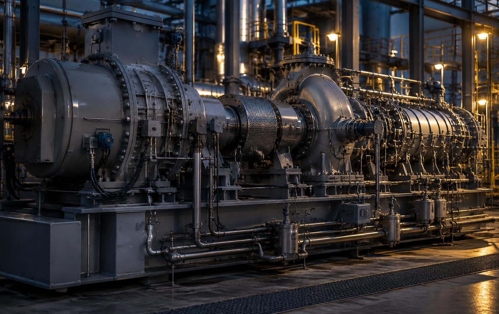
A train that couples a turbine driver, a turbo-expander and a centrifugal compressor is one of the highest-consequence assets in a process plant. The three machines share a shaft line, a lube and seal oil system, a protection rack and an outage window. A spreadsheet FMECA that scores each body in isolation will rank a drain valve beside a dry gas seal and still miss the auxiliary failure that trips all three. This article sets out the exact method BlackOut Power Group applies through its FMECA Criticality Guardian to build a train FMECA that is quantitative, severity-governed and executable in the CMMS.
01
The single-shaft vulnerability
In cryogenic gas processing, LNG, refinery and power-recovery service, the expander and compressor are often mechanically coupled, with a turbine or motor driver on the same line or through a gearbox. Torque, axial thrust, thermal growth and vibration cross every coupling. A liquid slug in the expander becomes a torsional event in the compressor; a thrust imbalance in the compressor loads the driver's thrust bearing.
The train also shares single points of failure that no body-level study owns: the API 614 lube and seal oil console, the dry gas seal supply and buffer system, the API 670 protection rack and the anti-surge control loop. Component-level FMECAs consistently under-rank these auxiliaries because, in isolation, a filter crossover or an accumulator bladder looks minor. In a train, either can trip the whole unit.
- Torsional coupling: transients in one body load every coupling, gear and shaft end.
- Thermal coupling: cryogenic or hot expander service against compressor and driver temperatures drives alignment and nozzle-load risk.
- Auxiliary coupling: one lube, seal gas and protection system serves all three machines.
- Outage coupling: any mode that stops one body stops the train and its downstream process.
An FMECA earns its cost only when its highest-consequence failure modes become specific, scheduled and verifiable work in the CMMS. Everything else is documentation.
02
Step 1 - Build the ISO 14224 taxonomy before scoring anything
The Guardian starts every train at the taxonomy, not the failure mode. Boundaries decide ownership: whether the coupling belongs to the driver or the compressor, whether seal gas conditioning sits with the compressor or the auxiliary system. Ambiguous boundaries are the most common source of duplicated and missing failure modes.
For the train, Level 4 equipment units are the turbine driver, the turbo-expander, the centrifugal compressor, the lube and seal oil system, the dry gas seal system and the machinery protection system. Level 5 subunits include rotors, radial and thrust bearings, dry gas seals, inlet guide vanes, couplings, balance piston and interstage labyrinths. Level 6 and below carry the maintainable items the CMMS will plan against.
ISO 14224 train taxonomy
- L1-L3Facility, plant and sectionGas processing plant, cryogenic recovery section
- L4Equipment unitsTurbine driver, turbo-expander, centrifugal compressor, lube and seal oil, dry gas seal system, machinery protection
- L5SubunitsRotors, radial and thrust bearings, dry gas seals, inlet guide vanes, couplings, balance piston, labyrinths
- L6-L8Maintainable items and partsSeal faces, thrust pads, servo actuators, probes, filters, accumulators
03
Step 2 - Escape the RPN trap with dual-metric criticality
IEC 60812 itself cautions that the risk priority number has weaknesses. Severity, occurrence and detection are ordinal scales, so multiplying them is not arithmetic on real quantities. A mode scored 10 x 2 x 5 and one scored 4 x 5 x 5 both return 100, although the first can destroy the rotor and the second is a nuisance.
The Guardian therefore runs two complementary metrics. RPN is retained for compatibility with IEC 60812 and SAE J1739 practice. Alongside it, the asset-level weighted criticality model combines six 1-to-5 ratings and scales them by a dependency multiplier that reflects how much of the process stops when the asset stops.
- Weighted base score
- Base = 0.20 Severity + 0.25 Business impact + 0.15 Detection + 0.15 Frequency + 0.10 MTBF risk + 0.15 Cost impact
- Final score
- Final = Base x Dependency multiplier (1.00, 1.10, 1.25 or 1.50), capped at 5.0. An unspared train on the main process line carries 1.50.
- Priority bands
- 4.0 and above: immediate RCA, RCM and capital review. 3.2 to 4.0: RCM and bad-actor review. 2.4 to 3.2: PM and PdM optimization. Below 2.4: basic PM or controlled run-to-failure.
- RPN bands
- RPN = S x O x D on 1-to-10 scales. 200 and above extreme, 120 to 199 high, 60 to 119 medium, below 60 low. Advisory only; severity governs.
Dual-metric criticality in the Guardian
- Weighted criticalityAsset levelSix weighted 1-5 ratings x dependency multiplier. Ranks which equipment deserves deep analysis.
- RPNFailure mode levelS x O x D on 1-10 scales per IEC 60812. Advisory; ordinal, so never decisive alone.
- Cm and CrQuantitativeMIL-STD-1629A: beta x alpha x lambda-p x t, summed per item. Used where failure data supports it.
- Severity overrideGoverningClass I/II, S 9 or higher, or RPN 200 or higher flags Critical regardless of arithmetic.
04
Step 3 - Quantify mode criticality with MIL-STD-1629A
Where failure data exists, the Guardian moves from ordinal scoring to quantitative criticality. MIL-STD-1629A Method 102 expresses the criticality of each failure mode as the expected number of failures producing the defined end effect over the evaluation period.
Cm = beta x alpha x lambda-p x t, where beta is the conditional probability that the mode produces the end effect, alpha is the fraction of item failures occurring in that mode, lambda-p is the item failure rate in failures per 10^6 hours and t is the operating time. Item criticality Cr is the sum of Cm across the item's modes. The engine refuses to publish a quantitative result if any of the four inputs is missing, which prevents a partially populated model from masquerading as quantitative.
For a train, lambda-p begins with ISO 14224-structured plant history and, where history is thin, with generic datasets used only as priors. The value of Cr is comparative: it identifies which subunit, typically seals, bearings or the oil system, concentrates the expected failure burden.
05
Step 4 - Let severity override arithmetic
No multiplication should be allowed to dilute a catastrophic consequence. The Guardian classifies each mode against MIL-STD-882E across safety, environmental, operational and economic axes, and the worst axis governs.
A mode is automatically flagged Critical when any one of three conditions holds: severity class I or II, a severity score of 9 or higher, or an RPN of 200 or higher. Impeller overspeed burst, dry gas seal blowout with process gas release, and thrust bearing failure with rotor-to-stator contact are flagged regardless of how improbable or detectable they appear on paper. The engine also raises three automatic gaps: a detection gap when a high-RPN mode has no detection method, a mitigation gap when it has no action, and a critical risk gap when a severity 8 or higher mode has no control at all.
06
Step 5 - Dissect failure modes by mechanism, body by body
A failure mode must name a physical mechanism and an observable symptom, not a vague condition. High vibration is a symptom; rotor unbalance from impeller fouling, sub-synchronous whirl or coupling misalignment are mechanisms with different detection methods and different tasks. The table below shows representative train modes as structured in the Guardian worksheet.
| Body / subunit | Failure mode and mechanism | Effect at train level | Primary detection | S / O / D |
|---|---|---|---|---|
| Turbine driver - governor / trip valve | Valve stem sticking from deposits or varnish | Loss of speed control; overspeed protection impaired | Partial stroke test, valve position deviation | 10 / 3 / 6 |
| Turbine driver - blading | High-cycle fatigue cracking from resonance or erosion | Blade liberation, forced outage, casing damage | Vibration spectra, borescope, steam path inspection | 10 / 2 / 6 |
| Turbine driver - thrust bearing | Babbitt fatigue or wipe from axial overload | Axial displacement trip, rotor contact | API 670 axial position, bearing metal temperature | 9 / 3 / 3 |
| Turbo-expander - wheel | Erosion from liquid droplet or solids carryover | Efficiency loss, unbalance, wheel failure | Inlet separator level trend, vibration 1x, efficiency trend | 8 / 4 / 5 |
| Turbo-expander - inlet guide vanes | Linkage binding at cryogenic temperature | Loss of flow control and process upset | Command versus position deviation | 7 / 4 / 4 |
| Turbo-expander - rotor | Sub-synchronous instability from seal or bearing forces | Rising sub-synchronous vibration, trip | Proximity probe spectra and orbit analysis | 8 / 2 / 4 |
| Compressor - dry gas seal | Face contamination from liquids or particulates in seal gas | Primary seal leakage, process gas release, trip | Primary vent flow and pressure trend, seal gas filter dP | 10 / 4 / 4 |
| Compressor - aerodynamics | Surge from anti-surge valve or controller failure | Thrust reversal, seal and bearing damage | Anti-surge controller logs, valve stroke test | 9 / 3 / 5 |
| Compressor - balance piston | Labyrinth wear increasing leakage | Thrust bearing overload, efficiency loss | Balance line pressure, thrust bearing temperature | 8 / 4 / 4 |
| Lube and seal oil system | Filter or cooler changeover pressure dip | Low lube oil pressure trip of the whole train | Changeover procedure, pressure transmitter trend | 8 / 3 / 6 |
| Lube and seal oil system | Oil varnish and contamination | Valve sticking, bearing distress across all bodies | Oil analysis, MPC varnish testing, ISO 4406 counts | 7 / 5 / 5 |
| Machinery protection | Probe or channel failure, unsafe or spurious | Undetected damage or nuisance trip | Rack diagnostics, loop and trip testing | 9 / 3 / 7 |
07
Step 6 - Walk every mode through SAE JA1011 decision logic
Task selection is not a matter of preference. The Guardian walks each mode through the JA1012 questions: is the failure evident to operators in normal duty, does it carry a safety or environmental consequence, does it carry an operational consequence, is a measurable P-F interval known, and is the failure age-related.
Hidden failures with safety or environmental consequences, such as an overspeed trip valve that will not close or a surge protection loop that will not act, receive a failure-finding task at a calculated interval. Run-to-failure is never accepted for them. Evident safety failures go to condition-based tasks where a P-F interval exists, scheduled restoration or discard where the failure is age-related, and mandatory redesign where neither applies.
SAE JA1011 / JA1012 task selection
Hidden + safety or environment
Failure-finding task at calculated interval. Run-to-failure not acceptable.
Hidden, no safety consequence
Failure-finding if economically justified, otherwise redesign.
Evident + safety or environment
Condition-based if P-F known, then scheduled restoration or discard, otherwise redesign.
Evident + operational
Condition-based or time-based if justified, otherwise run-to-failure.
Evident, no consequence
Run-to-failure is the default acceptable outcome.
08
Step 7 - Validate every interval against the P-F curve
A condition task is only valid if it inspects often enough to catch degradation before functional failure. The Guardian enforces a task interval no greater than half the P-F interval, so at least one inspection falls inside the warning window. A monthly oil sample against a two-week varnish-to-sticking progression fails this test regardless of how good the laboratory is.
For hidden functions, the failure-finding interval is commonly approximated as FFI = 2 x MTBF x (tolerable unavailability), which ties test frequency directly to the protective function's demonstrated reliability rather than to a calendar habit.
P-F interval validation
- P1Earliest detectable changeSub-synchronous vibration, seal vent flow, oil varnish potential
- P2Confirmed potential failureTrend exceeds alert band; planned intervention window opens
- Interval ruleTask interval no greater than P-F / 2At least one inspection falls inside the warning window
- FFunctional failureTrip, seal leakage, bearing wipe or loss of process function
09
Step 8 - Price the exposure for the boardroom
Engineering rank and financial exposure must be read together. For each mode the Guardian computes exposure as the occurrence-derived probability multiplied by downtime cost per hour and impact duration, plus any one-off repair or replacement cost. For an unspared train feeding a gas plant, downtime cost usually dominates the repair bill by an order of magnitude.
The boardroom view then shows open and closed actions, residual RPN after mitigation, percentage risk reduction and the remaining exposure by body. That is the language capital committees and owners act on, and it keeps the FMECA connected to the capital prioritization discipline described in our enterprise portfolio work.
10
Step 9 - Package tasks and turn them over to the CMMS
Selected tasks are bundled into craft-specific, outage-aligned packages: online vibration and process-data monitoring, operator rounds, periodic oil and seal gas sampling, trip and failure-finding tests, and a major overhaul scope aligned to the train's turnaround window.
The Guardian exports structured worksheets to Excel and CSV and a formal report, ready to load as functional locations, equipment records, task lists, maintenance plans and spare-part references in SAP PM or IBM Maximo. Engineering Records Intelligence and PDF.TerraTolga reconcile P&ID tags, datasheets and vendor documents against the asset hierarchy so the CMMS receives clean master data rather than another spreadsheet.
Guardian FMECA to CMMS pipeline
- 01
ISO 14224 taxonomy
- 02
Guardian FMECA worksheet
- 03
Criticality and severity override
- 04
JA1011 task selection
- 05
P-F interval validation
- 06
Task packaging
- 07
SAP PM / Maximo load
- 08
RCFA and MOC feedback
11
Step 10 - Keep the FMECA alive
A train FMECA decays from the day it is approved. Management of change, rerates, seal upgrades, control logic edits and new operating envelopes all invalidate assumptions. The program stays credible only when every RCFA finding, MOC and quarterly bad-actor review writes back to the master model.
The Guardian flags bad actors automatically when failures reach four per year or actual MTBF falls to 60 percent of target or less, and re-bands MTBF risk from the actual-to-target ratio. Responsible Engineer review closes the loop: AI-assisted suggestions in the tool remain drafts until an engineer accepts, edits or rejects them.
- Delta review on every MOC that touches the train, its auxiliaries or its operating envelope.
- RCFA findings update the failure mode, mechanism, occurrence and detection scores.
- Quarterly bad-actor and residual-risk review against CMMS work history.
- Annual recalibration of failure rates and P-F intervals from plant data.
Related Capability
Continue Reading
- The 58-MW Rolls-Royce Trent Gas Turbine - Repair, Replace, Monitor
Machinery Diagnostics
- From 10,000 Initiatives to the 10 Programs That Matter
Asset & Transaction Advisory
- From Contract Award to Defensible Closeout: An Owner’s System for Construction Control, Quality and Operational Readiness
Owner's Engineering / Construction Management
Technical References
Standards basis and scope references.
- 01 IEC 60812, Failure modes and effects analysis (FMEA and FMECA), for procedure and the documented limitations of the risk priority number.
- 02 MIL-STD-1629A, Task 102, for quantitative mode criticality (Cm) and item criticality (Cr). The standard is cancelled for new defense work but remains a widely used analytical reference.
- 03 MIL-STD-882E for severity categories I to IV used to classify consequence independently of likelihood.
- 04 SAE JA1011 and JA1012 for reliability-centered maintenance evaluation criteria and decision logic, including failure-finding and P-F interval principles.
- 05 ISO 14224 for equipment taxonomy, boundary definitions and reliability data collection; OREDA-type datasets as a starting point for failure rates where plant history is insufficient.
- 06 API 617 (axial and centrifugal compressors and expander-compressors), API 612 or API 616 (steam or gas turbine drivers), API 614 (lubrication, shaft-sealing and oil-control systems), API 670 (machinery protection) and API 692 (dry gas sealing systems), as adopted by the project.
- 07 ISO 17359 for condition monitoring and diagnostics, and ISO 20816 for vibration evaluation where adopted.
- 08 OEM manuals, trip philosophy and repair limits govern machine-specific settings. Scores, failure rates and intervals in this article are illustrative and must be set from plant data and OEM requirements.
Applicability and adopted editions must be confirmed against the governing contract, authority, location, cable construction, and manufacturer requirements.