
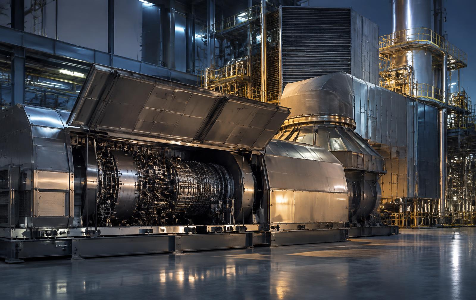
In a 90-MW cogeneration island, a 58-MW aeroderivative gas turbine is not an isolated generator. It is the thermodynamic source for the heat recovery steam generator, the steam turbine and the host process. Every decision to wash it, repair it, exchange the core or replace the package changes electrical output, exhaust energy, steam production and contractual steam supply at the same time. The engineering question is never only what failed. It is which intervention restores the whole system at the lowest lifecycle cost and the lowest residual risk.
01
The cogeneration island is one machine, not three
A representative configuration pairs a 58-MW aeroderivative gas turbine with a heat recovery steam generator, often supplementary fired, whose steam combines with process steam to drive a 32-MW steam turbine while extraction or letdown steam serves the host facility. Electrical output, steam export and host process stability are all downstream of one exhaust stream.
Exhaust mass flow and exhaust temperature are the real product of the gas turbine in this arrangement. Lose corrected airflow through compressor fouling or opened clearances and the HRSG loses duty. Shift exhaust temperature and the high-pressure superheat, pinch point and attemperation behaviour move with it. Duct-burner fuel can mask the loss for a while, at a fuel cost the plant model rarely shows until the reconciliation is done.
That is why a gas turbine decision in cogeneration must be evaluated on a heat and mass balance, not on megawatts. A replacement unit that meets the electrical rating and misses the exhaust flow or temperature window can leave the steam host short and the steam turbine operating outside its swallowing capacity.
Cogeneration energy chain
- 01
Fuel gas
Metered energy input at controlled pressure, temperature and Wobbe Index
- 02
58-MW gas turbine
Electrical output plus exhaust mass flow and exhaust temperature
- 03
Exhaust duct and duct burner
Backpressure limit, supplementary firing and flow distribution
- 04
Heat recovery steam generator
High-pressure and low-pressure steam at a duty set by exhaust energy
- 05
32-MW steam turbine
Additional generation limited by steam quality and swallowing capacity
- 06
Host process steam
Contractual extraction or letdown supply that cannot be interrupted
Corrected performance tells you how much capability is gone. Only mechanism tells you whether washing, repairing, exchanging the core or replacing the package will bring it back.
02
What goes wrong, and how it is actually detected
Degradation and failure in these packages fall into recognizable families, each with its own detection method. The value of a structured monitoring program is that the detection method is defined before the event, not improvised during the outage.
| System | Typical failure or degradation | How it is detected |
|---|---|---|
| Inlet and filtration | Filter loading, media damage, moisture carryover, icing, silencer or duct debris | Inlet differential pressure trend, corrected airflow loss, visual and internal inspection |
| Compressor | Fouling, erosion, corrosion pitting, tip rub, variable vane schedule drift, blade distress | Compressor pressure ratio, corrected airflow and efficiency, wash response, borescope, vane schedule verification |
| Fuel gas system | Filter or coalescer loading, liquids carryover, Wobbe Index drift, valve seat leakage, strainer blockage | Fuel gas chromatograph, supply pressure and temperature, valve position versus flow, leak and stroke testing |
| Ignition and combustion | Failed exciter or igniter, nozzle coking or erosion, flame instability, dynamics excursion | Flame scanner behaviour, start reliability, dynamic pressure transducers, exhaust spread |
| Combustors and hot section | Liner cracking, coating loss, oxidation, creep, thermal barrier coating spallation, nozzle distress | Exhaust temperature spread and margin, borescope, life-limited part cycle counting |
| Turbine and power turbine | Efficiency loss, seal and clearance opening, blade damage, foreign or domestic object damage | Corrected heat rate, gas path analysis, exhaust temperature margin, borescope |
| Rotor and bearings | Unbalance, misalignment, rub, bearing wear, oil whirl, thrust load change | Proximity probes and accelerometers per API 670, orbit and spectrum analysis, axial position, bearing metal temperature |
| Lubrication | Contamination, water ingress, varnish, wear metals, cooler or pump degradation | Oil analysis and ferrography, ISO 4406 cleanliness, supply pressure and temperature, filter differential pressure |
| Gearbox and coupling | Tooth wear, coupling fatigue, misalignment-driven load | Vibration spectra at mesh frequencies, oil debris, alignment records, torque and thermal growth checks |
| Exhaust and HRSG interface | Expansion joint failure, duct leakage, backpressure increase, flow maldistribution | Exhaust backpressure trend, duct thermography, HRSG steam production versus predicted duty |
| Generator | Insulation degradation, partial discharge, cooling loss, excitation faults | Partial discharge monitoring, winding and bearing temperature, insulation resistance and polarization index |
| Controls and protection | Sensor drift, logic or setpoint error, actuator response loss, protection channel failure | Loop checks, redundant channel comparison, trip and permissive proof testing |
| Enclosure, fire and gas | Ventilation loss, detector failure, suppression readiness, gas accumulation | Ventilation flow verification, detector function testing, suppression system inspection |
03
Corrected performance separates recoverable loss from real damage
Raw output means nothing without correction. Ambient temperature, barometric pressure, humidity, fuel composition and heating value, inlet and exhaust pressure loss and load point all change what the machine can produce. Corrected output, corrected heat rate, compressor pressure ratio, corrected airflow, exhaust temperature and exhaust temperature margin are the working parameters.
Gas path analysis then attributes the loss. Reduced corrected airflow with an intact pressure ratio points toward inlet restriction or compressor fouling. Reduced compressor efficiency with airflow loss points toward fouling, erosion or clearance change. Turbine efficiency loss with rising exhaust temperature at constant load points toward hot-section deterioration or leakage. A widening exhaust temperature spread points toward combustion maldistribution or nozzle and thermocouple problems. Instrument bias must be excluded before any of it is believed.
The practical test is a controlled offline water wash followed by a repeatable performance run under comparable conditions. Recovered performance confirms fouling. Unrecovered performance confirms permanent deterioration and moves the question from cleaning to repair, core exchange or replacement.
- Corrected output
- Power at reference ambient and fuel conditions, the basis for guarantee comparison under ASME PTC 22.
- Corrected heat rate
- Fuel energy per unit output, the direct link between degradation and operating cost.
- Exhaust temperature margin
- Remaining thermal headroom before the control system limits firing, a leading indicator of hot-section condition.
- Exhaust temperature spread
- Circumferential distribution across the thermocouple rake, sensitive to combustion, nozzle and instrument faults.
04
A three-spool aeroderivative does not vibrate like a heavy frame
The Trent aeroderivative architecture uses independent low-pressure, intermediate-pressure and high-pressure spools with a free power turbine driving the generator through the load coupling. Each spool runs at its own speed, so diagnosis depends on tracking the running-speed order of the correct shaft rather than a single one-per-revolution component.
Machinery protection and diagnostics are built around API 670 practice: radial proximity or accelerometer channels appropriate to the bearing type, axial position monitoring, bearing metal temperature, and a phase reference for orbit and vector work. Unbalance, misalignment, rub, bearing distress, blade passing excitation and coupling problems each present differently across spool orders, and casing-mounted accelerometers carry the higher-frequency content that proximity probes cannot see.
Transient data is where aeroderivative machines reveal themselves. Startup and coastdown plots show critical speed response, changes in amplification factor, phase shifts and rub signatures that steady-state trends hide. A baseline transient set taken after every major intervention is the single most useful diagnostic asset an owner can hold.
Three-spool architecture and telemetry
- 01
LP spool
Low-pressure compressor and turbine, tracked at its own running-speed order
- 02
IP spool
Intermediate-pressure stage with an independent speed and vibration signature
- 03
HP spool
High-pressure core driving combustion air supply and hot-section duty
- 04
Free power turbine
Aerodynamically coupled output stage driving the generator train
- 05
Protection channels
Radial and axial position, bearing metal temperature and phase reference per API 670
- 06
Diagnostic channels
Casing accelerometers, dynamic pressure and transient startup and coastdown records
05
Four thresholds decide when the machine no longer qualifies
Operators often ask for one number that says the turbine is finished. There is no such number. There are four independent thresholds, each with a different owner, a different source document and a different consequence.
Confusing these categories is a common and expensive error. A performance code cannot set a trip. An OEM repair limit cannot certify regulatory compliance. An economic argument cannot override a safety interlock. The governing edition of every document, and the jurisdiction that adopts it, must be identified for the specific project.
Four intervention thresholds
Immediate safety
OEM control and protection specification; NFPA 85 and NFPA 37 as adopted
Mechanical acceptance
OEM repair, overhaul and life-limited parts criteria
Regulatory and code
ISO, API, ASME and permit requirements in the adopted edition
Performance and economics
ASME PTC 22 and the owner's lifecycle cost basis
| Threshold | Trigger | Governing source |
|---|---|---|
| A. Immediate safety | Overspeed, high vibration, axial displacement, bearing temperature, low lube pressure, flame failure, excessive exhaust spread, surge, fire or gas detection, ventilation loss, generator fault | OEM control and protection specification, safety interlock schedule, NFPA 85 and NFPA 37 as adopted |
| B. Mechanical acceptance | Crack indications beyond limit, coating loss, oxidation, creep, blade tip and seal clearance, rotor runout and balance, bearing condition, life-limited part cycles | OEM repair and overhaul manual and life-limited parts schedule |
| C. Regulatory and code | Emission permit limits, pressure part and piping compliance, electrical installation, machinery safety | ISO 21789, ISO 3977, API 616, API 614, API 670, ASME BPVC Sections I and IX, ASME B31.1, NFPA 70, site air permit |
| D. Performance and economics | Corrected output or heat rate below guarantee, insufficient exhaust energy for HRSG duty, process steam shortfall, emissions drift, poor start reliability, rising forced-outage rate, maintenance cost exceeding value | ASME PTC 22 for the unit, ASME PTC 46 or ISO 18888 for the plant, and the owner's economic basis |
06
Core exchange, package replacement and repowering are different projects
A gas generator core exchange is a configuration-control and interface exercise executed inside a short outage window using a lease or overhauled core. Success depends on interface compatibility, control software configuration, instrumentation matching, preservation condition and disciplined receipt inspection, not on new plant design.
A complete package replacement or a repowering with a different model is a new power-plant design problem. The design inputs must be settled before any model is selected, because the unit cannot be chosen on megawatts alone. The correct electrical output with the wrong exhaust flow or temperature is the wrong machine for a cogeneration island.
| Category | Required definition |
|---|---|
| Plant duty | Net and gross output, process steam demand by pressure level, operating profile, starts and ramping, base load versus cycling, minimum stable load, black-start requirement, availability and reliability commitments |
| Site conditions | Ambient range, elevation and barometric pressure, humidity, icing, airborne contaminants, seismic and wind criteria, noise limits, hazardous area classification |
| Fuel | Composition and heating value, Wobbe Index range, supply pressure and temperature, contaminants, compression or heating requirements, any future hydrogen blending intent |
| Thermodynamic matching | Exhaust mass flow and temperature, allowable exhaust backpressure, HRSG high-pressure and low-pressure steam production, duct-burner duty, steam turbine swallowing capacity, condenser and cooling limits, process extraction, water treatment capacity |
| Mechanical and civil | Static and dynamic foundation loads, footprint and maintenance clearances, inlet and exhaust ducting, shaft height and coupling arrangement, piping flexibility and allowable nozzle loads, lifting and module removal access |
| Electrical and controls | Generator voltage, frequency, power factor and reactive capability, short-circuit duty, transformer and switchgear ratings, synchronization and protection, grid code compliance, control system integration, cybersecurity, safety-instrumented and emergency shutdown functions |
| Commercial | Performance guarantees, maintenance intervals, long-term service agreement scope, spare core strategy, liquidated damages, testing obligations |
07
OEM interaction: what you buy, witness and refuse to sign
The strongest owner position on an aeroderivative asset is established in the purchase and repair scope, not during commissioning. Scope language determines whether the owner receives as-found borescope records, rotor balance data, dimensional and clearance reports, life-limited part histories, control configuration files and test data, or only a certificate.
An inspection and test plan classifies every point as Hold, Witness, Review or Surveillance. A hold point stops work until the owner or the owner's engineer releases it. A witness point invites attendance and allows work to proceed. A review point applies to documentation. A surveillance point permits unannounced inspection. Assigning these correctly is the difference between a governed shop scope and a hopeful one.
One caution matters more than any other in this class of machine. A standard controls or package factory acceptance test proves logic, loops, permissives and trips. It does not prove thermodynamic performance. Full-speed no-load running, string testing and a full-load performance test are separate purchases that must be written into the contract with the test code, the correction methodology and the acceptance criteria stated in advance.
Shop hold-point sequence
- H · Hold
Design basis and interface freeze
- R · Review
Material certification and PMI
- W · Witness
Welding, NDE and dimensional checks
- H · Hold
Rotor balance and clearance records
- W · Witness
Package assembly verification
- H · Hold
Baseline borescope
- H · Hold
Controls factory acceptance test
- H · Hold
Mechanical run or performance test, if purchased
- H · Hold
Preservation and shipping release
| Activity | Class | What the owner is protecting |
|---|---|---|
| Design basis and interface register | H | Frozen interfaces, duty and correction basis before manufacture or rebuild |
| P&ID, general arrangement, HAZOP and FMECA review | H / R | Safety and operability decisions captured before fabrication |
| Material certification and positive material identification | R / H | Traceable materials on hot-section and pressure-retaining parts |
| Welding procedures, qualification and NDE | R / W | Qualified procedures and independent examination records |
| Rotor assembly, dimensional check and high-speed balance | H / W | Balance state, runout and clearances recorded against OEM limits |
| Package assembly and clearance verification | W | As-built configuration matching the released drawings |
| Baseline borescope | H | Documented as-shipped internal condition before ownership transfer of risk |
| Lube system cleanliness and flushing certification | W | ISO 4406 cleanliness achieved before first rotation |
| Controls factory acceptance test | H | Logic, permissives, trips and loop integrity proven off site |
| Fire and gas system testing | W / H | Detection and suppression functionality demonstrated |
| Electrical and generator factory tests | W | Insulation, excitation and protection verified |
| Mechanical run or string test, if purchased | H | Vibration, thermal and bearing behaviour at speed before shipment |
| Performance test, if purchased | H | Corrected output and heat rate demonstrated against the stated code |
| Preservation, packing and shipping release | H | Protected condition, shock and tilt instrumentation, complete data book |
08
Installation and commissioning in ten controlled steps
Field execution is where a good procurement can still be lost. The sequence below is the governed path from engineering readiness to handover, with each step producing records that later become the monitoring baseline.
- 1. Engineering readiness. Freeze the design basis and interface register, close HAZOP and design review actions, issue commissioning procedures and confirm OEM acceptance criteria and correction methodology.
- 2. Isolation and removal. Apply lockout and tagout, drain and preserve systems, record as-found alignment, vibration and clearances, disconnect interfaces under an engineered lift plan and inspect foundations and ducting.
- 3. Receipt and preservation. Verify shock and tilt indicators, serial numbers and shipping damage, confirm preservation state and certificates, and perform a receipt borescope before acceptance.
- 4. Mechanical installation. Survey and level the foundation, position the package, set cold alignment to OEM thermal growth targets, verify piping nozzle loads and coupling alignment, and record torque, clearances and foreign material exclusion closure.
- 5. Precommissioning. Flush and certify the lube system, clean and test fuel and air piping, complete pressure and leak testing, verify fuel gas quality and valve stroking, megger and loop check electrical systems, and prove fire, gas, permissive, trip and emergency shutdown functions.
- 6. First rotation and first fire. Establish auxiliaries, run on turning gear, complete crank and purge cycles, establish ignition and stable flame, and monitor vibration, bearing temperature, oil condition and exhaust behaviour through defined speed plateaus to full-speed no-load.
- 7. Synchronization and loading. Match voltage, frequency and phase, synchronize, then load incrementally with vibration, combustion dynamics, temperature and emissions verified at each plateau.
- 8. Combined-cycle integration. Establish HRSG circulation and water chemistry, prove drains, vents, bypasses and attemperators, warm steam lines on controlled ramps, admit steam to the turbine and stabilize the plant heat balance and host extraction.
- 9. Acceptance. Complete emissions testing, corrected performance testing, the reliability run, start, trip and load-rejection demonstrations, punch list closure and new condition baselines.
- 10. Handover. Deliver as-built drawings and settings, complete records, CMMS asset hierarchy and maintenance strategy, spares, tools, training, warranties and the monitoring plan.
Cold-to-hot alignment control
- 01
Cold set
Deliberate offset applied at ambient so the train aligns hot
- 02
Thermal growth
Predicted vertical and axial movement from OEM growth data
- 03
Nozzle load
Piping strain checked so connected systems do not move the machine
- 04
Hot verification
Alignment and position confirmed after thermal stabilization
09
The tools that carry the work
Credibility in this environment comes from the toolchain as much as the theory. Performance and cycle work uses corrected gas path models and heat balance software. Rotordynamic and vibration work uses continuous monitoring systems with orbit, spectrum, transient and vector capability. Inspection uses measurement-capable videoprobes and borescopes, ultrasonic and eddy current methods, positive material identification and metallurgical examination where a failure is being investigated.
Alignment and geometry work uses laser alignment and laser tracker survey with documented cold-to-hot offsets. Lubrication uses particle counting to ISO 4406, wear metal analysis and ferrography. Fuel work uses online chromatography and Wobbe Index tracking. Outage and scope control uses Primavera P6, Microsoft Project and Deltek Acumen where the project warrants it.
Engineering Records Intelligence connects drawings, data books, inspection history, vendor documents and prior studies so decisions are made against the real configuration. TerraTolga Vault Compare identifies revision and basis changes between document sets. Criticality and FMECA structure the consequence and failure logic. SAP, IBM Maximo and client CMMS or EAM platforms carry the maintenance strategy and history. QC Lite, a BlackOut Power Group platform currently in development, is intended to track field work steps, hold points, signoffs and deficiency workflows during execution. Tools support engineering judgment. They do not replace it, and no tool substitutes for the OEM requirements and the accountable Responsible Engineer review.
- Performance
- Corrected gas path and heat balance analysis, ASME PTC 22 test planning and correction methodology.
- Mechanical
- Continuous vibration monitoring per API 670 practice, transient analysis, borescope and NDE, laser alignment and tracker survey.
- Fluids and materials
- Lube oil analysis and ISO 4406 cleanliness, fuel chromatography and Wobbe tracking, metallurgical examination when failure analysis is required.
- Information
- Engineering Records Intelligence, Vault Compare, Criticality, FMECA and CMMS or EAM integration for configuration and history.
10
Monitoring, baselines and the decision that follows
Long service life on an aeroderivative asset is produced by baselines, not by hope. After every intervention the owner should reset corrected performance baselines, steady-state and transient vibration baselines, clearance and alignment records, borescope imagery, lube and fuel condition references and protection setpoint records. Degradation is then measured against a known state rather than a memory.
Those baselines feed the maintenance strategy held in the CMMS: wash intervals driven by measured fouling response, borescope intervals driven by observed hot-section condition and cycles, life-limited part counting, oil sampling routes, protection system proof testing and critical spares held against defined outage exposure.
The final decision framework is simple to state and demanding to apply. Wash when the loss is recoverable. Repair when the mechanism is local and the remaining life supports it. Exchange the gas generator core when hot-section condition, cycles or outage duration make it the lowest lifecycle cost path. Replace or repower when the duty, the emissions basis or the steam host requirement has moved beyond what the installed machine can serve. Each of those conclusions must be supported by corrected data, mechanism evidence and a lifecycle cost comparison, reviewed by a Responsible Engineer before capital is committed.
Related Capability
Continue Reading
- From 10,000 Initiatives to the 10 Programs That Matter
Asset & Transaction Advisory
- From Contract Award to Defensible Closeout: An Owner’s System for Construction Control, Quality and Operational Readiness
Owner's Engineering / Construction Management
- A Pressure-Tight Joint Is Not a Durable Joint: Why Heat Exchangers Keep Leaking Before You Change the Alloy
Pressure Equipment / Owner's Engineering
Technical References
Standards basis and scope references.
- 01 ASME PTC 22, Gas Turbines, for corrected power output, heat rate, exhaust flow, exhaust energy and exhaust temperature. It is a performance test code and does not establish protective trip settings.
- 02 ASME PTC 46 and ISO 18888 for overall plant and combined-cycle performance testing, where the contract adopts them.
- 03 ISO 21789, Gas turbine applications - safety, and ISO 3977 series, including ISO 3977-8 for inspection, testing, installation and commissioning.
- 04 API 616 for gas turbines for the petroleum, chemical and gas industry services, API 614 for lubrication, shaft-sealing and oil-control systems, and API 670 for machinery protection systems.
- 05 ISO 20816 series for mechanical vibration measurement and evaluation on non-rotating parts, as adopted by the project or the OEM.
- 06 NFPA 85 and NFPA 37 for combustion and engine installation safety requirements, and NFPA 70 for electrical installation, as adopted by the authority having jurisdiction.
- 07 ASME BPVC Section I and Section IX, and ASME B31.1, for HRSG pressure parts, welding qualification and power piping where applicable.
- 08 OEM operation, maintenance and overhaul manuals, control philosophy and long-term service agreement documents govern trip setpoints, repair limits and life-limited part management. Where OEM requirements and general industry practice differ, the OEM and contract requirements control.
Applicability and adopted editions must be confirmed against the governing contract, authority, location, cable construction, and manufacturer requirements.