
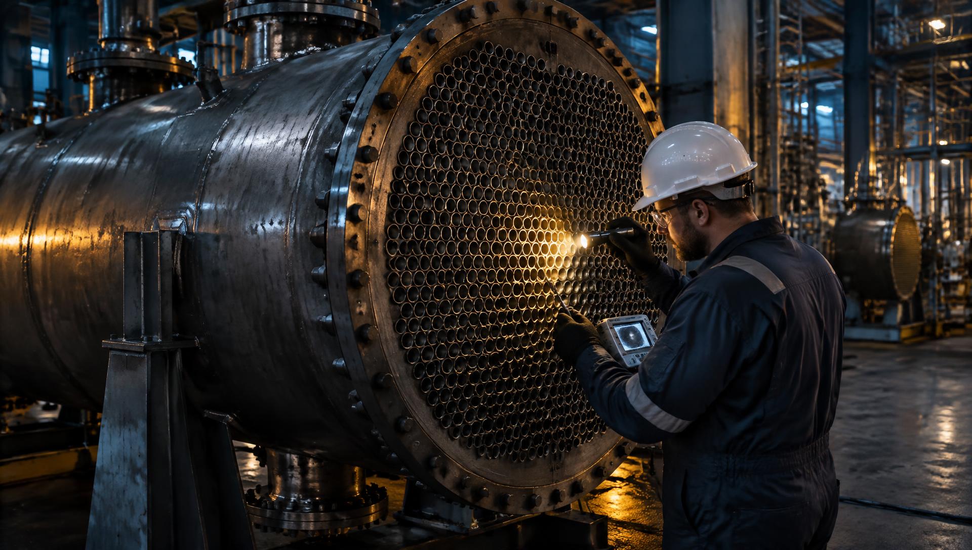
A vertical shell-and-tube exchanger in aggressive acid service starts leaking well before its expected life. Cooling water chemistry moves. Dissolved metals rise. Tubes are plugged, the unit is returned to service, and the same event repeats. Somewhere in the review, a familiar conclusion appears: the alloy was wrong, so specify something more expensive. That conclusion may be correct. It is frequently premature.
01
The exchanger leaks. The alloy is not the first question.
When a critical exchanger leaks early, the fastest available explanation is material selection. It is a comfortable answer because it converts an unresolved engineering problem into a purchasing decision. The difficulty is that a metallurgy change made without an established failure mechanism can reproduce the same failure in a more expensive unit.
The disciplined sequence is the opposite. Establish the service condition actually imposed. Establish the joint configuration and the fabrication record. Establish what the physical evidence shows. Only then decide whether the mechanism is material driven, fabrication driven, operation driven or some combination. A leak is an observation. A mechanism is a conclusion, and it has to be earned.
This article uses a generic representative case: a vertical shell-and-tube exchanger with an aggressive acid or process fluid on the tube side, cooling water on the shell side, interconnected carbon-steel cooling-water infrastructure downstream, long expected life and thin tube walls, where the tube-to-tubesheet joints are critical to containment. No project data, no client identity and no measured values from any real unit are presented. Actual metallurgy and damage depend on concentration, temperature, contaminants, chlorides, velocity, aeration, oxidizing or reducing conditions and process excursions.
Inspection confirms execution. Technical assurance challenges the basis of execution.
02
Define the service before defining the joint
Joint philosophy is a consequence decision, and consequence cannot be assessed without the service definition. The process basis should state the fluids, concentration range, contaminant envelope, temperature and pressure range, startup, shutdown, upset and cleaning conditions, and the expected frequency of excursions rather than only the steady-state design point.
Thermal design determines velocities, film temperatures, approach temperatures and the tube-wall temperature that the material actually experiences, which is often not the bulk fluid temperature. Mechanical design sets tubesheet thickness, ligament geometry, tube pitch and pattern, tube wall thickness, baffle spacing, expansion provisions and differential thermal growth between tubes and shell.
Material selection follows from those three, not the other way around. The most common weakness in a specification is that the corrosion envelope is written for the normal condition and never for the excursion, the cleaning cycle, the stagnant period or the shutdown condition where concentration, aeration or deposit chemistry can differ substantially.
- Design basis review
- Process, thermal, mechanical and materials reviewed together, including excursions, cleaning and idle conditions.
- Wall temperature
- Material suitability assessed at the metal temperature and local velocity, not only the bulk fluid condition.
- Consequence definition
- What one small in-leak does to the connected system, stated before the joint type is selected.
03
Tube-to-tubesheet joint configurations
The joint is a defined engineering configuration, and the terminology matters because acceptance criteria follow it. The common configurations are the expanded joint, the grooved and expanded joint, the seal welded and expanded joint, the strength welded joint, and the strength welded and expanded joint. The applicable code, standard and specification define which configurations are permitted for a given design and which are credited for load.
A seal weld addresses leak tightness at the joint face. A strength weld is credited for the mechanical load the joint must carry. They are not interchangeable terms, and a drawing that says only weld is an open technical question rather than a specification.
Grooving is a design decision about mechanical interlock and leak path length. Expansion depth relative to tubesheet thickness, the unexpanded land near the face and back face, and the ligament geometry between holes are all part of the same design intent. Changing any one of them without engineering review changes the joint.
- Expanded joint
- Tube expanded into the tube hole to develop contact pressure and leak tightness without a credited weld.
- Grooved and expanded
- Expansion into machined grooves to increase mechanical interlock and extend the leak path.
- Seal welded and expanded
- Expansion for contact and a face weld intended for leak tightness, not credited for mechanical load.
- Strength welded
- A weld designed and qualified to carry the mechanical load defined by the code of construction.
- Strength welded and expanded
- A credited weld combined with controlled expansion, with the expansion sequence relative to welding defined by the qualified procedure.
Tubesheet ligament
Material, thickness, cladding or overlay condition, and hole pattern govern the available support and the ligament stress around each joint.
Tube hole
Diameter, tolerance, surface finish and any grooving establish the geometry the expansion is intended to fill.
Expanded zone
The rolled length engages the hole and any grooves. Expansion is specified as a controlled wall reduction inside a qualified window.
Transition zone
The boundary between expanded and unexpanded tube concentrates residual strain and is a common location for service-related degradation.
Weld
A seal weld addresses leak tightness. A strength weld is credited for mechanical load. The two are not interchangeable.
Tube wall
Thin-wall tubing limits both the expansion range and the heat input a joint can tolerate without damage.
04
Consequence-driven joint philosophy
The question is not which joint is best in the abstract. The question is what the consequence of a single small in-leak is in this specific system, and whether the selected joint and its verification plan are proportionate to that consequence.
Where a small tube-side in-leak would introduce an aggressive fluid into a large carbon-steel cooling-water circuit, the consequence is not confined to one tube. It can reach pumps, piping, exchangers, control valves and cooling tower internals, and it can force chemistry intervention across the whole circuit. That consequence may justify a more conservative joint configuration, tighter qualification and a more capable leak detection strategy than the pressure rating alone would suggest.
Where the consequence of a small leak is limited and readily detected, a less conservative configuration with proportionate verification may be entirely defensible. Both answers are engineering answers. What is not defensible is selecting the joint by habit and then discovering the consequence in service.
05
Controlled expansion: the qualified window
The objective of tube expansion is not maximum expansion. It is controlled expansion within a qualified window. Under-expansion may leave insufficient contact pressure and an incomplete seal, with a crevice that can support concentration and localized attack. Over-expansion may produce excessive wall reduction, tube thinning, work hardening, residual stress, ligament distortion or damage at the transition between expanded and unexpanded tube.
Wall reduction is the controlling parameter in most specifications, expressed as a target range with tolerance, measured on qualification joints and verified during production. The specific percentage is a project and qualification matter, governed by the tube material, wall thickness, hole geometry and the fabricator's qualified procedure. It should not be adopted from a generic number found in a handbook.
The transition zone deserves specific attention. It is the location where geometry, residual strain and process chemistry can intersect, and in many service-related investigations it is where the physical evidence is most informative. Over-rolling does not automatically produce cracking, and a claim that it does is not supportable as a general statement. What is supportable is that expansion outside the qualified window changes the joint from the one that was engineered.
06
Mock-up qualification before production
Do not use the owner's exchanger as the experiment. Prove the joint first. For critical service, the most valuable single control available to an owner is a representative mock-up qualified and destructively examined before the first production joint is made.
A useful mock-up reproduces the variables that matter: the actual tube material, size and wall thickness from the production lot where practical, the actual tubesheet material and thickness or a representative section, the same hole preparation, tolerance and grooving, the same expander and roller configuration, the same expansion parameters, the same welding procedure, sequence and heat input, and the same operator qualification and production sequence.
Mock-up destructive qualification of this kind is generally an owner or specification requirement for critical service rather than a universal code mandate. It should be written into the purchase specification and the inspection and test plan deliberately, with acceptance criteria defined in advance, because a qualification without pre-agreed criteria becomes a negotiation after the fact.
Mock-up qualification sequence
- 01
Prepare representative mock-up
- 02
Measure tube and tube hole
- 03
Install tube
- 04
Set expansion parameters
- 05
Expand tube
- 06
Measure expansion and wall reduction
- 07
Weld if specified
- 08
NDE
- 09
Leak and pressure test
- 10
Mechanical test as applicable
- 11
Section the joint
- 12
Mount, polish and etch
- 13
Macro examination
- 14
Measure fusion and geometry
- 15
Examine tube deformation
- 16
Determine acceptance
- 17
Release production procedure
07
Destructive examination: what sectioning shows that hydro cannot
Sectioning a qualification joint answers questions that no pressure test can answer. Macro examination after mounting, polishing and etching can reveal weld fusion and penetration, the geometry of the expanded zone, the sharpness or smoothness of the transition, the degree of groove fill, the actual wall reduction achieved, the presence of gaps or crevices, and fabrication indications such as lack of fusion, undercut, cracking or porosity.
Supporting examinations may include metallography for microstructure and heat-affected zone condition, hardness traverses, dimensional verification of the expanded zone, and mechanical tests such as pull-out or push-out where the specification requires a load-related result. Leak and burst testing may be included where the qualification program calls for them. Which of these are code required, specification driven or good practice varies by the code of construction and the contract, and the program should state the basis for each test rather than implying that all of them are mandatory everywhere.
The value is not the individual test. It is the combination of geometric, metallurgical and mechanical evidence establishing that the production procedure, as written and as executed, produces the joint the designer intended.
08
Seal weld and strength weld are different engineering decisions
More penetration is not automatically better. A weld is qualified to a procedure for a reason. Increasing heat input or penetration beyond the qualified condition can alter the heat-affected zone, distort the tube end, affect the adjacent expanded zone, and in some materials influence sensitization or corrosion behavior.
The engineering questions are whether the weld is credited for load, whether the welding procedure and performance qualifications cover the actual joint configuration and position, whether the sequence of welding relative to expansion is defined, and whether the examination method can actually detect the defect types that matter at that joint geometry.
Where a seal weld is specified, it should be described and accepted as a seal weld. Where load must be carried, the weld must be designed, qualified and examined as a strength weld. Conflating the two in the specification or in the fabrication records is one of the more consequential documentation defects found during owner review.
09
Rolling machine control is a manufacturing process, not a task
Tube expansion should be treated as a controlled manufacturing process with defined inputs, verification and records. That includes the expander type and size, roller condition and wear, mandrel condition, lubrication, torque or pressure setting where a torque-controlled or pneumatic expander is used, expansion depth and sequence, and calibration of the control equipment.
Verification is dimensional. ID measurement before and after expansion, bore gauges, micrometers and wall thickness measurement establish the achieved wall reduction against the qualified target. The first qualification joints establish the production window. Drift in that window during production, caused by roller wear, setting changes, operator change or a different tube lot, is a legitimate reason to stop and requalify.
The records matter as much as the measurements. A joint-by-joint or defined-sample record tied to tube position allows a later investigation to compare the physical evidence with the fabrication condition at that specific location instead of relying on recollection.
10
Production surveillance and hold points
An inspection and test plan should include hold points that cannot be passed without the owner's release where the consequence justifies it. The plan should state who witnesses, what the acceptance criteria are, what record is produced, and what happens when a criterion is not met.
The conventional inspector asks whether the inspection and test plan was followed. That is a necessary question. The owner's technical assurance role asks two further questions: was the plan built around the correct engineering premise, and were the acceptance criteria capable of detecting the failure mechanism that matters for this service.
A plan that verifies dimensional conformance and pressure tightness but never verifies expansion inside the qualified window, or never examines a representative joint section, can be fully complied with and still fail to protect the owner.
- Design and specification review before fabrication release.
- Tube-hole machining, tolerance, finish and grooving verification.
- Material receipt, traceability and positive material identification.
- Welding and expansion procedure qualification review.
- Mock-up qualification and destructive examination witness.
- First production joint verification and production window confirmation.
- In-process rolling and welding surveillance with dimensional records.
- Nondestructive examination and leak testing witness.
- Hydrostatic or pneumatic test witness with instrument calibration verified.
- Final documentation and manufacturing record review before release for shipment.
11
Material verification and the limits of field methods
Positive material identification confirms that the material installed is the material specified. Portable X-ray fluorescence is effective for many alloying elements but is unreliable for light elements, including carbon, which means it cannot by itself distinguish grades that differ primarily by carbon content. Optical emission spectroscopy is used where carbon or low-atomic-number verification matters.
Material verification should cover tubes, tubesheet, cladding or overlay where used, weld filler material and, where relevant, gaskets and fasteners. Mill test reports should be reconciled to heat numbers and to physical marking, not accepted as a package.
Portable hardness testing can support verification of heat treatment condition or unexpected work hardening, within the known limitations of the method and the surface condition. Where a question cannot be resolved in the field, laboratory sampling and metallography are the defensible path rather than an assumption.
12
Factory testing and what it does not prove
A hydrostatic test demonstrates pressure integrity under the test condition. It does not, by itself, prove long-term durability. A joint can pass a hydrostatic test and still have insufficient contact pressure, a crevice, marginal fusion, excessive wall reduction or a transition geometry that will not survive thermal cycling and process chemistry.
Sensitivity is also a question. Where very small leakage rates matter, helium mass-spectrometer leak testing or other high-sensitivity methods may be warranted in addition to the code hydrostatic test, because the detectable leak rate of a hydrostatic test is comparatively coarse.
The owner's question is therefore not only whether the test passed, but whether the test performed was capable of detecting the condition that would matter in service, and whether the test conditions, differential direction and instrument calibration were appropriate to the design.
13
The manufacturing record baseline before shipment
Before the exchanger leaves the shop, the owner should hold a consolidated manufacturing record: design and code documentation, material certifications and traceability, welding and expansion procedure qualifications, operator qualifications, mock-up qualification report with macro images and measurements, tube-hole and expansion dimensional data, nondestructive examination reports, pressure and leak test records with calibration, nonconformance reports and their engineering dispositions, and the as-built tube map.
This record is the reference for every later question. Without it, a service leak produces argument. With it, the leak can be compared against a known fabrication condition at that location.
Engineering Records Intelligence and TerraTolga Vault Compare are used to organize, index and compare fabrication and turnover documentation across revisions so that a missing qualification, an undocumented change or a superseded procedure is found during review rather than during a claim.
14
Transport, storage and site receipt
Equipment condition can change between the shop and the foundation. Shipping restraint, lifting and handling, nozzle protection, desiccant and preservation, internal dryness, closure integrity and storage duration and environment all affect the unit that is finally commissioned.
Site receipt should be a defined technical activity: reconcile the shipment against the manufacturing record, inspect protection and preservation, document condition photographically, verify closures and tags, and record any deviation before the unit is accepted into storage.
Where preservation has lapsed or storage has extended well beyond plan, a documented re-inspection and, where warranted, re-testing is more defensible than assuming that a factory result still represents the current condition.
15
Commissioning baseline and vertical orientation specifics
Commissioning is the last opportunity to record a clean baseline while the unit is known good. That baseline should include installed condition, alignment and support, connected chemistry, pressure and temperature instrument verification, initial performance data and an initial cooling-water chemistry reference.
Vertical orientation is not a defect. It does, however, change some practical questions. Venting and gas accumulation, drainage and complete draining during shutdown, flow distribution and the possibility of stagnant or low-velocity regions, condensate or liquid holdup, and access for later tube inspection are all orientation sensitive. These should be addressed in the commissioning plan rather than discovered during the first upset.
Where stagnant regions or incomplete draining are plausible, the operating and shutdown procedures deserve the same review as the design, because a corrosion mechanism that only activates during idle periods will not be visible in normal operating data.
16
Early leak detection and multi-signal trending
A single alarm is weak evidence. A coordinated change across several independent signals is strong evidence. Cooling-water conductivity, pH, ORP where applicable, ion-specific measurement where the process fluid provides a distinctive tracer, dissolved metals trending, inhibitor demand, corrosion probe and coupon response, differential pressure, temperature approach and heat-transfer performance should be trended together.
The objective is detection at the earliest defensible point, because the cost of a small in-leak is driven largely by how long it continues before it is recognized. A leak that is identified in hours is a tube problem. A leak that runs for weeks can become a cooling-system problem.
Instrumentation selection should include the practical details that determine whether the measurement survives: sample conditioning, representative sample location, calibration interval, response time, and enclosure and area-classification suitability. NEMA 250 enclosure types and the IEC IP equivalents describe the environmental protection provided, and NFPA 70 area classification governs where the installation is in a classified area.
17
System consequence of a small leak
The reason early detection matters is that the consequence is rarely local. Where an aggressive tube-side fluid enters a cooling-water circuit, the chemistry change can affect carbon-steel piping, pumps, valves, other exchangers and tower internals well beyond the leaking unit.
Whether and how far a given system progresses along that path depends on the leak rate, the buffering and volume of the circuit, the treatment program, the detection interval and the response. The cascade below is illustrative of a plausible progression, not a prediction for any specific system.
The cost is rarely the tube. The cost is the system consequence and the outage required to reach it.
System consequence of a small leak
- 01
Tube or joint leak
- 02
Acid enters cooling water
- 03
Cooling-water chemistry excursion
- 04
Carbon-steel corrosion
- 05
Corrosion products and fouling
- 06
Pump, piping, valve and tower exposure
- 07
Heat-transfer degradation
- 08
Higher treatment demand
- 09
Additional equipment damage
- 10
Tube plugging or retubing
- 11
Production loss
- 12
Premature capital expenditure
18
In-service tube inspection matched to the material
No single tube inspection method detects every mechanism, and method selection is material dependent. Applying the wrong method produces a clean report that means very little.
Coverage strategy matters as much as method. A statistically meaningful sample stratified by position, flow region, temperature zone and prior findings is usually more informative than a large random sample, and the inspection plan should state how the sample was chosen.
| Method | Typical application | Principal limitations |
|---|---|---|
| Eddy current testing | Non-ferromagnetic tubing such as austenitic stainless, nickel alloys, copper alloys and titanium | Reduced effectiveness in ferromagnetic material, sensitivity varies with defect orientation and support-plate signals |
| Remote field testing | Ferromagnetic tubing such as carbon steel and ferritic material | Lower resolution for small volumetric defects, slower, geometry sensitive |
| Partial saturation or near-field variants | Duplex and partially magnetic materials where conventional eddy current is degraded | Requires careful setup and calibration to the specific material condition |
| Internal rotating inspection system | Quantitative wall-thickness profiling in many materials | Slow, requires clean tubes and water coupling, access dependent |
| Conventional and phased array ultrasonic | Local wall assessment, tubesheet and weld areas where access allows | Access, coupling and geometry constraints at the joint |
| Videoscope and borescope | Visual condition of tube ID, joint face, deposits and obvious damage | Surface only, no wall quantification |
| Pressure, vacuum and helium leak location | Locating which tube or joint is leaking | Identifies location, not mechanism or remaining life |
19
The first leak is the best evidence you will ever have
The common response to a first leak is to locate it, plug the tube, restart and move on. That response destroys the most informative evidence available and defers the engineering question to a future outage where the evidence will be worse.
A defensible first-leak response preserves the condition. Record the location on the tube map, photograph the joint face and surrounding tubes, capture the operating and chemistry data around the event, retain deposits and corrosion products, and where the consequence justifies it, pull a tube for laboratory examination rather than plugging blind.
Pulled-tube forensics requires chain of custody. Identify the tube, document its position, protect the ends, avoid cleaning that removes the evidence, and transfer the specimen with a written record. Laboratory examination can include visual and stereo microscopy, sectioning, metallography, scanning electron microscopy with elemental analysis, deposit analysis and dimensional measurement, compared where practical against a known-good control tube of the same design and production history.
20
The repeated-plugging trap
Plugging is a legitimate short-term measure. It becomes a trap when it is the only measure. Each plugging cycle reduces surface area and changes flow distribution, can increase velocity in the remaining tubes, and consumes the margin available for the next event, while the mechanism continues unaddressed.
There is also a records problem. Plugged tube positions, dates and reasons are frequently recorded informally or not at all. Without that history, a later investigation cannot establish whether the failures are clustered by position, by lot, by operator, by flow region or by fabrication sequence, which is exactly the pattern information that separates a fabrication mechanism from an operating mechanism.
A plugging log maintained in the maintenance system, with position, date, evidence and disposition, converts a series of isolated interventions into a dataset. That is a CMMS and engineering-data discipline as much as a mechanical one.
21
The alloy decision, after the mechanism
Failure mechanism first. Metallurgy second. Once the mechanism is established, a material change may be the correct answer, and it should then be specified with the same rigor as the original design: corrosion data for the actual concentration, temperature, contaminant and velocity envelope including excursions, galvanic compatibility with connected materials, fabricability and weldability, joint configuration implications, availability and delivery, and inspectability with the methods the owner intends to use.
Material changes carry second-order consequences. A different tube material can change the applicable nondestructive examination method, the expansion behavior and qualified window, the welding procedure, the thermal expansion differential with the tubesheet and shell, and the galvanic relationship with the rest of the circuit. A change that solves one mechanism can enable another.
No general claim is made here that any particular alloy is suitable for acid service. Suitability is a service-specific determination supported by corrosion data and, where warranted, testing.
22
Design basis and the code split: Section VIII Division 1 tube side, near-atmospheric water side
In the representative case, the tube side is designed and fabricated as a pressure-retaining part under ASME BPVC Section VIII Division 1, with material, welding, examination and hydrostatic testing per the code and the applicable edition adopted by the jurisdiction. The cooling-water shell side operates at or near atmospheric pressure. That asymmetry changes the way the joint should be assessed.
A low-pressure water side does not reduce the containment duty of the tube-to-tubesheet joint. The joint separates two fluids whose mixing has a chemical consequence, and the differential direction means that a small defect tends to carry the aggressive fluid toward the water side. The joint is therefore a process-safety and asset-integrity boundary, not only a pressure boundary.
It also affects testing and relief. Test pressure and the differential direction are established by the code of construction and the design conditions for each side, and a test that pressurizes only the high-pressure side does not necessarily challenge the joint in the direction that matters in service. Overpressure protection on the low-pressure side deserves explicit review where a tube rupture could pressurize it. A small acid in-leak is a chemistry event before it is a pressure event, which is precisely why chemistry monitoring, not pressure monitoring, is usually the detecting instrument.
- Tube side
- Designed, fabricated, examined and tested as a Section VIII Division 1 pressure boundary, with the joint configuration credited per the code.
- Shell water side
- At or near atmospheric operating pressure, with design pressure, relief and tube-rupture scenarios reviewed explicitly rather than assumed benign.
- Joint duty
- Assessed against chemical consequence and differential direction, not only against the pressure rating.
23
How much rolling is allowed: the basis for expansion limits
Questions about permissible expansion have a documentary answer, and it is distributed across several sources rather than contained in one number. The code of construction governs what joint types are acceptable and what credit they carry. ASME Section VIII Division 1 addresses tube-to-tubesheet joints, including the provisions commonly referenced as UW-20 and the non-mandatory appendix addressing expanded joints and their qualification, which is the path by which joint efficiency and qualification testing are established.
TEMA, in the RCB section, provides the dimensional framework: tube-hole diameter and tolerance for the applicable class, permitted grooving, expansion length relative to tubesheet thickness, and the ligament considerations that limit how aggressively adjacent holes can be expanded. Those dimensional provisions are the practical constraint on how much expansion the geometry can tolerate.
API 660 and ISO 16812 function as purchaser supplementary requirements that frequently tighten the code and TEMA baseline for refinery and petrochemical service. Above all of them sits the fabricator's qualified expansion procedure and the project specification, which state the target wall reduction, the acceptable range and the measurement method for that specific tube, tubesheet and hole combination.
The practical answer to how much rolling is allowed is therefore: the amount established by the qualified procedure for this joint, within the dimensional limits of the applicable standard and the code of construction, verified by measurement and recorded. A wall reduction percentage copied from another project is not a qualification.
24
Codes, standards and where each requirement comes from
Disputes about exchanger quality are often disputes about requirement source. A statement that something is required means very little until it is clear whether the requirement comes from the code of construction, an industry standard, the purchaser's specification, a recommended practice or an engineering judgment. The table below separates them for the topics discussed here. Applicability, edition and jurisdiction are always contract and authority specific.
| Topic | Typical source | Character of the requirement |
|---|---|---|
| Pressure design, materials, welding, examination and hydrostatic test | ASME BPVC Section VIII Division 1, with Sections IX and V | Code of construction where adopted |
| Tube-to-tubesheet joint acceptability and joint qualification path | ASME BPVC Section VIII Division 1 tube-to-tubesheet provisions and related appendix | Code of construction |
| Tube-hole diameter, tolerance, grooving and expansion geometry | TEMA RCB for the applicable class | Industry standard, commonly invoked by contract |
| Supplementary shell-and-tube requirements for process service | API 660, ISO 16812 | Purchaser specification when invoked |
| Mock-up qualification with destructive examination | Project specification and inspection and test plan | Purchaser requirement or recommended practice, not a universal code mandate |
| Damage mechanism identification and in-service inspection planning | API 571, API 510, AMPP/NACE guidance | Recommended practice and inspection code where adopted |
| Repair and alteration of the installed unit | National Board Inspection Code and jurisdictional rules | Regulatory where adopted |
| Monitoring instrument enclosure and area suitability | NEMA 250 enclosure types, IEC 60529 IP, NFPA 70 area classification | Product standard and installation code |
| Hold-point selection, evidence sufficiency and acceptance-criteria challenge | BPG owner-side assurance methodology | Engineering methodology, applied on top of the above |
25
Tools, software, equipment and NDE used across the determination
BPG experts use and evaluate industry-standard tools and test methods appropriate to the assurance or investigation scope. No claim is made that BPG owns every instrument listed. Mention of a manufacturer or method does not imply exclusivity or endorsement. What matters in both owner inspection and forensic investigation is that the method is capable of answering the question asked, that it is calibrated and applied by a qualified operator, and that the raw data and setup are retained.
Fabrication and dimensional control uses torque-controlled and pneumatic tube expanders with roller and mandrel condition control, tube-hole gauges, bore gauges, ID and OD micrometers, ultrasonic wall-thickness gauges, surface finish comparators and digital dimensional and inspection equipment. These produce the wall-reduction and geometry evidence that establishes whether the joint is inside the qualified window.
Material verification uses positive material identification by portable X-ray fluorescence, with its known light-element limits, optical emission spectroscopy where carbon or low-atomic-number verification matters, portable hardness testing, and laboratory metallographic sectioning, mounting, polishing, etching and macro examination. These establish what the material actually is and what condition it is in.
Welding and nondestructive examination uses visual inspection, liquid penetrant examination, radiography and ultrasonic examination where applicable, phased array where the geometry and access warrant it, borescope and videoscope inspection, and weld macro examination with fusion and penetration measurement. These establish whether the weld is the weld that was qualified.
Pressure and leak work uses hydrostatic and pneumatic test equipment with calibrated instrumentation, helium mass-spectrometer leak detection for high-sensitivity requirements, and halogen or vacuum techniques where applicable. In-service tube inspection uses eddy current for non-ferromagnetic tubing, remote field for ferromagnetic tubing, internal rotating inspection for wall profiling, conventional and phased array ultrasonic for local assessment, videoscope inspection and tube-side leak location methods, each selected for the material and the mechanism.
Operating monitoring uses pH and conductivity transmitters, ion-specific analyzers, ORP, linear polarization resistance and electrical-resistance corrosion probes, coupon racks, dissolved-metals sampling, differential pressure, temperature and flow instrumentation, and online chemistry platforms, specified with the enclosure and area-classification ratings the installation requires. Engineering analysis and data work uses thermal and mechanical analysis, process simulation, corrosion and material-selection references, FMECA and criticality methods, and BPG Engineering Records Intelligence and TerraTolga Vault Compare for fabrication-record and turnover-package review.
- Wall reduction verification
- Bore gauges, ID micrometers and ultrasonic thickness measurement compared against the qualified expansion window.
- Joint geometry evidence
- Sectioning, mounting, polishing, etching and macro examination with fusion and penetration measurement.
- Material confirmation
- XRF for most alloying elements, OES where carbon verification is required, reconciled to heat numbers.
- Leak sensitivity
- Helium mass spectrometry where the detectable leak rate of a hydrostatic test is insufficient for the consequence.
- Condition monitoring
- Corrosion probes, coupons, ion-specific analyzers and chemistry trending with defined sample conditioning.
- Records analysis
- Engineering Records Intelligence and TerraTolga Vault Compare for revision comparison across fabrication documentation.
26
Levels of owner-side assurance
Not every exchanger justifies the full program. Scope should be selected by criticality and consequence, and the owner should be able to state which level was applied and why.
- Level 1, documentation and specification review: design basis, material selection, joint configuration, inspection and test plan and acceptance criteria reviewed before fabrication release.
- Level 2, fabrication surveillance: procedure qualification review, hold-point witnessing, dimensional and rolling records, NDE and test witness, manufacturing record verification.
- Level 3, qualification and verification engineering: mock-up qualification design, destructive examination witness and interpretation, independent evaluation of acceptance criteria against the governing failure mechanisms.
- Level 4, operational assurance and investigation: commissioning baseline, monitoring strategy, first-leak response protocol, pulled-tube forensics, root cause determination and corrective-action verification.
Owner-side assurance lifecycle
- 01
Design review
- 02
Material selection
- 03
ITP review
- 04
Mock-up qualification
- 05
Fabrication surveillance
- 06
Rolling control
- 07
Welding verification
- 08
NDE and leak testing
- 09
Factory acceptance
- 10
Shipping and site receipt
- 11
Commissioning
- 12
Operating baseline
- 13
Performance monitoring
- 14
Failure investigation
27
Responsible Engineer review
Every conclusion of technical consequence issued by BlackOut Power Group is reviewed by a Responsible Engineer before release. Review confirms that the conclusion is supported by the evidence in the record, that the limitations and assumptions are stated, that standards are cited with their correct scope and edition, and that alternative explanations were considered and addressed.
This applies equally to owner-side assurance findings and to forensic conclusions. A finding that cannot be traced to the evidence that supports it is not issued.
28
The economics, stated plainly
The cost of a premature exchanger failure is rarely the tube. It is the system consequence, the treatment and remediation of a contaminated circuit, the collateral damage to connected equipment, the production interruption and the outage required to reach the unit. Those costs are typically incurred long after the decisions that caused them.
Owner-side assurance is a decision about where engineering effort is spent. Review before fabrication, qualification before production and surveillance during manufacture are comparatively small efforts positioned at the point where they can still change the outcome. After commissioning, the same questions cost far more to answer and can usually only be answered with the unit out of service.
29
Before the first production joint is made
A leaking exchanger needs a proven explanation, not an automatic material change. No metallurgy upgrade should be committed until the fabrication and operating mechanism is understood and controlled, because an unexplained mechanism will follow the equipment into its replacement.
The owner's exchanger should not be the first place the process is proven.
Engineer the joint. Qualify the process. Destroy the mock-up. Examine the evidence. Control production. Monitor operation. Investigate the first abnormality.
BPG can be the owner's eyes, ears and technical foothold from specification through service.
Related Capability
Continue Reading
Technical References
Standards basis and scope references.
- 01 ASME Boiler and Pressure Vessel Code, Section VIII Division 1, including tube-to-tubesheet joint provisions such as UW-20 and the non-mandatory appendix addressing expanded joints. Edition and addenda as adopted by the jurisdiction and the contract.
- 02 ASME BPVC Section IX, welding and brazing qualification, and Section V, nondestructive examination.
- 03 TEMA Standards, RCB section, including tube-hole diameter and tolerance, grooving and expansion provisions for the applicable class.
- 04 API Standard 660, shell-and-tube heat exchangers, as a purchaser supplementary specification.
- 05 API 571 damage mechanisms, API 510 pressure vessel inspection, and the National Board Inspection Code for repair and alteration jurisdiction.
- 06 ISO 16812, petroleum, petrochemical and natural gas industries, shell-and-tube heat exchangers.
- 07 ASTM tube material and dimensional specifications applicable to the selected material, and AMPP/NACE corrosion and materials guidance.
- 08 NEMA 250 enclosure types and the IEC 60529 IP equivalents for monitoring instruments, with NFPA 70 area classification where the installation requires it.
Applicability and adopted editions must be confirmed against the governing contract, authority, location, cable construction, and manufacturer requirements.