
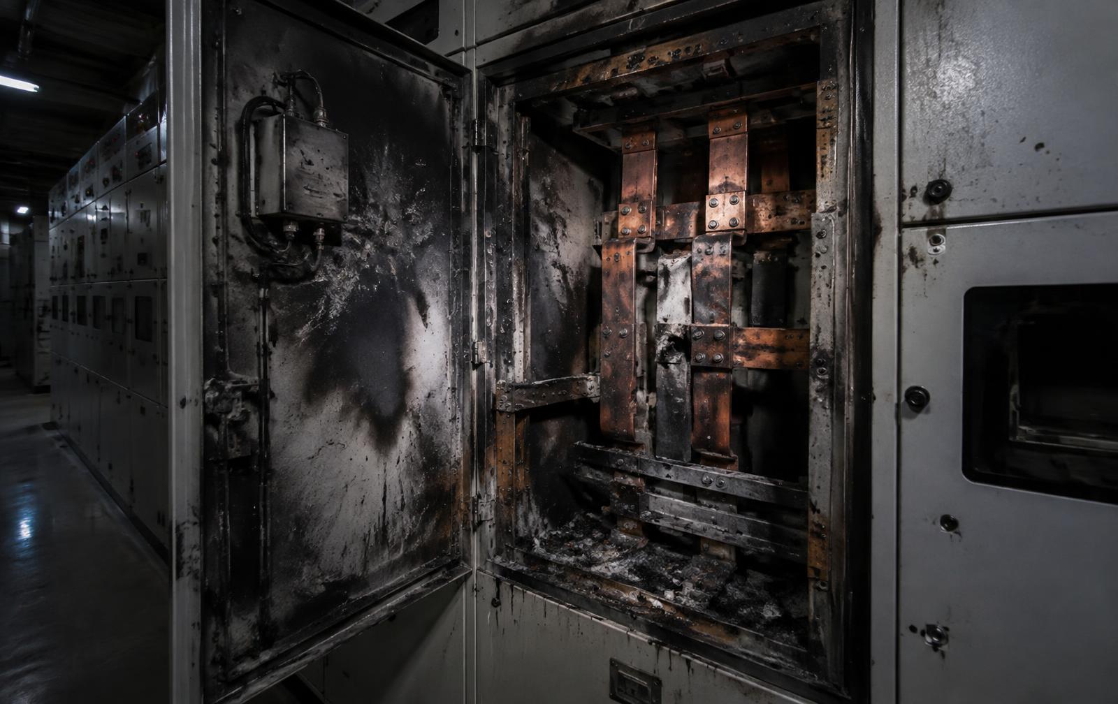
An arc flash may last a fraction of a second, but the condition that created it may have been developing for months or years. The event destroys the equipment that recorded it, and the remaining evidence is distributed across relays, meters, gas monitors, breaker mechanisms, maintenance files and the geometry of the damage itself.
01
The flash is the end of the process, not the beginning
The most defensible categorical statement about switchgear is this. An arc fault begins with a loss of electrical separation, most commonly through insulation breakdown, a deteriorated connection, contamination or an inadvertent conductive path. The severity of what follows is then governed by available fault current, protection performance and clearing time.
Those are two different questions and they need two different investigations. Fault initiation asks why the arc started. Protection analysis asks why the event developed the way it did. An investigation that stops at the point of greatest damage answers neither one, because the point of greatest damage records where the energy was released, not where separation was first lost.
That distinction decides whether a report can survive cross examination. It also decides whether the corrective action prevents recurrence or simply replaces the equipment that happened to absorb the energy.
A damaged switchgear lineup tells you where the energy was released. It does not tell you where the failure began.
02
Loss of electrical separation: five field condition families
Field conditions that destroy separation fall into a small number of families. Ranking them statistically is unnecessary and rarely defensible. What matters is that each family leaves different evidence and each is disproved differently.
The useful division is between equipment precursor conditions, which develop over time and are in principle detectable, and interaction initiated events, which occur during human work on or near energised equipment. Both produce an arc. Only one of them should have been visible in advance.
- Insulation system
- Aged or cracked insulation, carbon tracking, damaged bus insulation, deteriorated cable terminations, partial discharge activity, contamination by dust, oil or process residue, moisture and condensation, and clearances reduced below design.
- Connections
- Bolted joints, bus splices, cable lugs and breaker contacts that loosen through vibration or thermal cycling. The sequence is consistent: increased contact resistance, localised heating, further deterioration, insulation damage, arcing. Sometimes the arc begins years earlier as a slightly deteriorated connection.
- Contamination and environment
- Conductive dust, moisture ingress, condensation from failed space heaters, corrosion, process contaminants, animal or foreign material intrusion, and enclosures whose rating no longer matches the environment they sit in.
- Mechanical condition
- Switchgear is not purely electrical. Racking systems, shutters, interlocks, breaker mechanisms, bus supports and insulators, fasteners, contact pressure and alignment all deteriorate, and a mechanically deteriorated component can create the electrical condition that eventually arcs.
- Human interaction
- Racking operations, energised troubleshooting, test probes, misapplied grounding devices, incorrect wiring and work near exposed energised parts can create an instantaneous phase to phase or phase to ground path with no detectable precursor at all.
03
SF6 and gas insulated equipment: what the gas records
In gas insulated switchgear the insulating medium is itself an instrument. Sulphur hexafluoride holds off voltage in a compartment far smaller than air insulation would allow, and its condition is monitored continuously because the equipment depends on it. That monitoring history is evidence.
Density and pressure trends, alarm and lockout records and refill history establish whether the compartment was losing gas before the event, and how long that had been tolerated. Moisture content indicates seal or desiccant condition. Where an internal arc has occurred, the gas carries a chemical signature: decomposition by-products such as sulphur dioxide, thionyl fluoride and hydrogen fluoride confirm that arcing took place inside a sealed compartment and give an indication of its severity, even when the compartment has not been opened.
The consequence side is equally important. Sulphur hexafluoride is a potent and long lived greenhouse gas, and a compartment breach or pressure relief operation releases it directly. An internal arc in gas insulated equipment is therefore both a technical event and a reporting event, with recovery, handling and emissions accounting obligations that follow from it. Decomposition by-products are also toxic and corrosive, which changes how the equipment can be entered, how evidence is preserved and how the restoration scope is priced.
None of this is available once the equipment is cut open, purged and cleaned. Gas evidence is among the first things lost in a hurried restoration.
04
Protection performance decides how bad it gets
The relay did not cause the insulation to fail. But relay settings, current transformer response, breaker operating and clearing time, protection coordination and available fault current together determine whether the event lasts a few cycles or develops into destruction of an entire lineup.
That makes protection performance part of the causation question, and frequently the part that decides allocation of responsibility. It is also the part most often assumed rather than tested. The coordination study describes what settings should have been in place. Only the as found settings file and secondary injection results establish what was actually in service on the day.
- Available fault current at the point of the fault, compared with the study basis and any change in source impedance since it was performed
- As found relay settings and logic compared with the issued coordination study and the last approved settings revision
- Current transformer ratio, saturation and wiring, which can delay or defeat an otherwise correct scheme
- Breaker operating and clearing time measured against the manufacturer curve, not the nameplate
- Selectivity between upstream and downstream devices, and whether coordination intentionally extended the event
- Whether arc flash mitigation was available and in service, including maintenance mode, zone selective interlocking, arc flash relays and light and pressure detection
05
Reading the physical record
Physical evidence establishes direction, duration and sequence when it is examined before cleaning and disposal. Damage geometry is read as a record of energy transfer, not as a map of blame.
- Arc roots and erosion
- Conductor erosion patterns and root locations that indicate where the arc attached and how it migrated along the bus.
- Copper deposition
- Vaporised and redeposited metal that traces arc travel, plasma direction and the compartments through which the event propagated.
- Tracking and carbonisation
- Surface tracking on insulation, standoffs and supports distinguishing a developing path from post event contamination.
- Thermal gradients
- Discolouration, annealing and melting thresholds used to bound temperature and duration at separate locations.
- Mechanical and blast effects
- Door, latch and pressure relief behaviour compared with the internal arc classification the equipment was supplied to.
- Breaker and mechanism
- Contact condition, wear, mechanism state and racking interface examined as found, with position at the moment of the event established where possible.
- Terminations and metallurgy
- Cable lugs, joints and fractured components examined metallographically to separate pre existing deterioration from arc damage.
06
The investigation framework
The framework below separates the questions that are commonly collapsed into one. Each step produces findings that constrain the next, and each can be tested independently by an opposing expert.
- 01 Find the initiating condition. Insulation, connection, contamination, mechanical deterioration, foreign object or human intervention, each supported or excluded on evidence.
- 02 Reconstruct the electrical sequence. Relay targets, sequence of events records, waveform captures, metering, breaker operation and upstream utility data, aligned across systems whose clocks rarely agree.
- 03 Read the physical damage. Arc roots, conductor erosion, copper deposition, tracking, thermal damage and blast effects, examined before the equipment is disturbed.
- 04 Test the protection response. Did the scheme identify the correct fault, did the breaker clear on time, and did coordination extend the event.
- 05 Ask whether precursor evidence existed. Thermal anomalies, partial discharge activity, gas density alarms, repeat breaker problems, deferred maintenance, prior inspection findings and unresolved alarms.
- 06 Define how recurrence is prevented. Inspection strategy, condition monitoring, protection changes, maintenance practice, equipment modification or replacement, applied across sister equipment as well as the unit that failed.
07
What the investigation is measured with
Conclusions in an electrical failure investigation rest on measurement, not impression. The instruments below are the ones that convert an opinion about a switchgear event into a record another engineer can verify.
- Infrared thermography and thermal trending across joints, terminations, bus connections and breakers, with historical surveys reviewed rather than a single post event image
- Insulation resistance and polarisation index testing, and power factor or tan delta testing where the apparatus supports it
- Partial discharge survey and continuous monitoring, including ultrasonic, transient earth voltage and high frequency current transformer techniques
- Circuit breaker timing, travel, contact resistance and dynamic contact resistance testing against manufacturer curves
- Protective relay secondary injection, settings verification and event record extraction, with COMTRADE waveform analysis
- SF6 density, moisture, purity and decomposition by-product analysis, with recovered gas mass documented for emissions reporting
- Torque and connection verification, grounding and bonding checks, and enclosure and environmental condition assessment
- Laser scanning and photogrammetric capture of the as found lineup before demolition, preserving geometry that cannot be recreated
- Metallurgical examination of arc affected conductors, fasteners and fractured components
- Short circuit, coordination and incident energy modelling reconciled against the measured event rather than against the design assumption
08
What the failure actually costs
The technical conclusion drives commercial consequences that are usually larger than the switchgear itself. Establishing them early changes how the matter is managed.
Medium voltage equipment carries long lead times, and an obsolete lineup may not be replaceable in kind at all. The exposure is rarely the panel. It is the period during which the plant cannot run at full capability.
- Equipment loss and replacement lead time, including obsolescence where in kind replacement is no longer available
- Unplanned outage and lost production for the period the distribution capability is degraded, and the cost of any temporary supply
- Personnel injury exposure and the regulatory review that follows an arc flash incident
- Environmental release and reporting obligations where gas insulated equipment was breached
- Insurance causation and coverage position, including whether damage is attributable to the event or to pre existing deterioration
- Restart approval, code compliance and the evidence required before the lineup is re energised
- Recurrence risk across sister equipment of the same vintage, environment and maintenance history
09
Was the condition visible before the event
This is the question that decides most disputes and most prevention programmes. An investigation that identifies the initiating condition but never asks whether it was detectable leaves the most valuable finding on the table.
Where a precursor existed, the record usually holds it: a thermographic anomaly that was noted and not corrected, partial discharge activity trending upward, a gas density alarm reset repeatedly, a breaker with a history of mechanism problems, connections never retorqued after a known thermal event, or an environmental control that had failed long before.
BlackOut Power Group examines both sides of that line. What the wreckage establishes about the event, and what an effective electrical inspection and condition monitoring programme should have identified before it. The first supports the claim or the dispute. The second is what keeps the same lineup from failing again.
Related Capability
Continue Reading
- It's Not Just a Gasket: Eliminating Flange Leaks Through Bolted Joint Engineering, Controlled Bolting, and Assembly Governance
Pressure Systems
- Spring Hangers: Selection, Setting, Inspection and the Failures They Prevent
Machinery Diagnostics
- Criticality Is Not Priority: How Engineering Leaders Decide What Work Comes First
Asset Advisory