
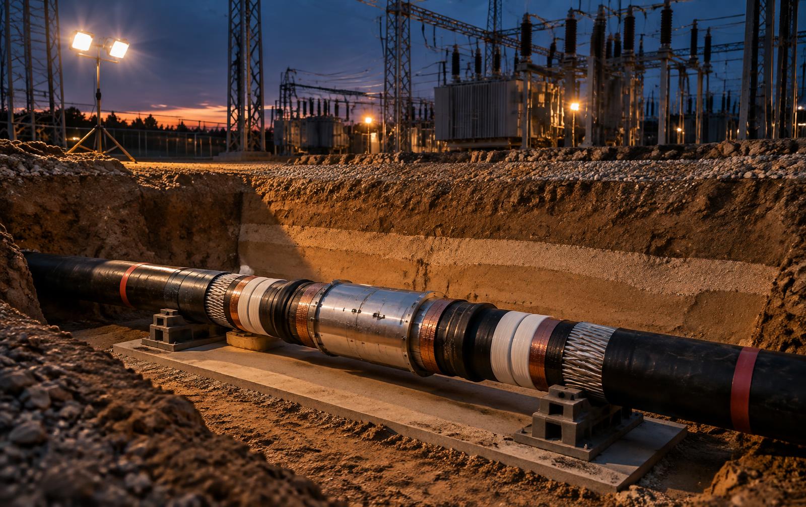
At 115 kV, restoring electrical continuity is the easy part conceptually. The engineering challenge is proving why the original cable failed, whether the installation environment contributed, and whether the repaired cable system, including the new joint, can safely survive another several decades.
01
The first question is not how to splice it
When a 115-kV underground circuit faults, the operational pressure is immediate and the instinct is to locate the damage, cut it out, install a joint and return the circuit to service. That sequence can be correct. It is only correct once a second question has been answered.
Why did the cable fail? Until that is established, the repair is a decision made without knowing what it is repairing. If excavation reached the cable, a new joint restores the circuit and leaves the exposure exactly where it was. If the thermal environment no longer matches the rating assumptions, a new joint is installed into the same overheating condition. If the failure initiated inside a previous accessory, then installing another accessory built the same way is a scheduled repeat.
This is why a cable repair at transmission voltage belongs to failure investigation before it belongs to construction. The cause determines the scope of the repair, not the other way round.
At transmission voltage, a splice is manufactured in the field. The worksite temporarily becomes part of the cable factory.
02
Competing causal families
Several mechanisms can put a 115-kV cable on the ground, and they leave different evidence. A defensible investigation carries all of them forward until the physical and electrical record eliminates them, rather than adopting the first plausible story.
Note that several of these can be present together. External damage to the oversheath years earlier and moisture ingress later are one sequence, not two competing hypotheses, and the investigation has to be able to say which was the initiating event and which was the consequence.
- External Intrusion
- Excavator, auger, directional drill or pile contact. Evidence is localised mechanical deformation, tool marks, a fresh disturbance profile in the trench and a fault record consistent with an instantaneous event rather than a developing one.
- Installation Damage
- Excessive pulling tension, sidewall pressure at bends, violation of minimum bend radius, jacket abrasion or contact with sharp rock. The NESC addresses control of bending, pulling tension and sidewall pressure during installation for exactly this reason. Damage can be decades old before it produces a fault.
- Thermal Environment
- An underground cable depends on the surrounding soil and engineered backfill to dissipate heat. IEEE 442 addresses measurement of soil and backfill thermal resistivity because those properties govern rating and loading, and IEC 60287 provides the rating framework. Drying, settlement, native soil substitution or a later parallel service can erode thermal margin without anyone changing the load.
- Moisture Ingress
- Oversheath or metallic sheath damage admitting water into the insulation system. Evidence includes sheath fault location history, corrosion products, water tracing in the layers and, in the laboratory, water treeing morphology.
- Bonding and Sheath Currents
- Incorrect bonding or cross bonding, an open or shorted link box, or a failed sheath voltage limiter. This raises circulating current and sheath potential, adds heat and can damage the oversheath. It is also one of the few causes still measurable after the repair.
- Insulation Deterioration or Manufacturing Defect
- Contaminants, voids or protrusions in the extruded insulation, or aging under service stress. This is established by sectioning and microscopy of the failure region and of undamaged reference lengths from the same reel, not by age alone.
- Accessory or Prior Repair Defect
- A joint or termination is the least factory controlled element of the circuit, and after laying testing exists precisely because installation defects in accessories can survive commissioning. If the failure is at or near a previous accessory, that accessory is the first hypothesis, not the last.
03
Why a splice at 115 kV is a different object
At 480 V, a splice is largely understood as connecting two conductors. At 115 kV, the conductor connection is one function out of eight.
The cable leaves the factory as a set of carefully engineered concentric layers: conductor, conductor screen, insulation, insulation screen, metallic screen or sheath, water barrier and jacket. Cutting the cable interrupts that entire dielectric system. The field joint has to rebuild electrical continuity, insulation, electric field control, screen and sheath continuity, grounding and bonding, mechanical integrity, environmental sealing and thermal performance, simultaneously, in a trench.
This is recognised engineering practice, not improvisation. IEEE 404 establishes ratings and test requirements for shielded power cable joints from 2.5 kV through 500 kV, so a qualified 115-kV joint is a designed and tested product. NESC Rule 333 carries the same principle into the field, requiring cable accessories and joints to withstand the mechanical, thermal, environmental and electrical stresses expected in service, to maintain the structural integrity of the cable, and to withstand expected fault current conditions.
The correct conclusion is therefore narrow and important. Splicing a 115-kV cable is neither unsafe nor inferior. An improperly selected, prepared, installed or tested splice is the risk.
04
Workmanship creates new dielectric interfaces in the field
This is where the engineering gets interesting and where most disputes eventually land. Preparing a high voltage extruded cable for a joint creates new dielectric interfaces that did not exist in the factory product, and those interfaces are assembled by hand under site conditions.
Small imperfections matter at this stress level. A contaminant, a scratch on the insulation surface, an incorrect semiconductive screen cutback, an out of tolerance dimension, a void, insufficient interfacial pressure, the wrong lubricant or a misplaced field grading element will distort the electric field locally. Distorted field leads to localised stress, which can lead to partial discharge, electrical treeing and eventual breakdown, on a timescale that can run from weeks to years.
CIGRE guidance on high voltage accessories consistently emphasises the same variables: electric field control, material interfaces, interface smoothness and pressure, cleanliness, and the training and tooling of jointing personnel. None of that is optional detail. It is the reason two physically identical joints can have entirely different service lives.
05
The ground around the cable is part of the electrical system
Most people looking into the trench see dirt. The cable engineer sees four systems at once: mechanical protection, thermal pathway, moisture environment and future excavation exposure.
For direct buried cable, NESC Rule 352A addresses the trench bottom, requiring relatively smooth earth, well tamped earth or sand, and protective well tamped backfill where the excavation is through rock or rocky soil. Backfill is not to damage the cable and is to be adequately compacted to limit settlement. On depth, NESC Rule 352D and Table 352-1 list 42 inches, 1,070 mm, for supply cable or duct operating above 50 kV, with reduced depth permitted where suitable supplemental mechanical protection is provided, and with recognition of final grade and surface use.
Here is the distinction that generic cable articles miss. Burial depth addresses mechanical exposure. Thermal backfill addresses ampacity and service life. They solve different problems and neither substitutes for the other. IEEE 442 exists because cable loading depends on the ability of the surrounding medium, whether soil, sand, engineered backfill, grout or concrete, to move heat away from the conductor. Returning excavated native soil to the trench may therefore be entirely inadequate where the design assumed controlled thermal backfill.
A serious repair asks three questions about the ground itself. Was the original backfill mechanically suitable? Was its thermal resistivity consistent with the rating assumptions? Did settlement, drying or a later excavation change those conditions after commissioning?
- Cable, on a prepared bedding that will not damage the sheath
- Controlled thermal and mechanical bedding around the cable
- Engineered backfill selected for thermal resistivity, not convenience
- Protective mechanical layer such as a slab, cover or duct bank where the specification calls for it
- Route warning and identification system at the specified height above the cable
- Normal compacted fill to final grade
06
Code minimum and specification practice are not the same thing
Precision matters here, because overstating a code requirement is the fastest way to lose an argument. The NESC sets minimum burial depth, addresses bedding and backfill, and permits supplemental mechanical protection where appropriate. Warning slabs, concrete covers, duct banks, controlled thermal backfill and route marker systems are frequently required by utility standards and project specifications, and they are good engineering, but they are specification practice rather than universal code minimums.
That distinction becomes a root cause finding. If excavation damage caused the failure, repairing the cable without improving the excavation barrier restores the circuit and restores the vulnerability with it. The corrective action in that case is not the joint. It is the protective layer, the marker system and the locate process that failed to keep a machine away from an energised transmission cable.
07
Before anyone touches the cable
A transmission cable retains capacitive charge and can carry induced or backfeed voltage from parallel circuits even when the terminals are open. The repair therefore begins inside the owner's approved switching, clearance, isolation and grounding procedures, and those procedures are part of the repair engineering, not a preliminary to it.
OSHA 29 CFR 1910.269(m) governs the de-energising process for generation, transmission and distribution work, including system operator clearance and testing for absence of voltage. 1910.269(n) addresses protective grounding and the establishment of an equipotential zone, and specifically addresses work on cable remote from its terminal because of transfer potential hazards. High voltage testing is addressed separately under 1910.269(o), which matters because the repair ends with a test that re-energises the cable at elevated voltage.
Stated plainly for the record: at 115 kV, the breaker being open is not a safe work condition. Isolation, verification, discharge, grounding and control of induced potential are engineered steps with documentation behind them.
08
The repair is a controlled QA and QC operation
A crew should not arrive and make a joint. The work should run from a controlled work package built for the specific cable and accessory combination in front of them, because that is the only way workmanship can be demonstrated after the joint is closed and buried.
AEIC CS9 covers transmission class extruded cables and accessories above 46 kV, and AEIC CG4 addresses installation of extruded dielectric power cable systems rated 69 kV and above. Between those and the accessory manufacturer's qualified procedure, every dimension and hold point in the joint has a defined acceptance value. The purpose of the work package is to convert those values into a record.
- Accessory selection verified against the actual cable construction, insulation diameter and conductor size, with the qualification evidence on file
- Qualified and demonstrably trained jointers, named on the package
- Environmental controls: tent, heat, humidity and dust control appropriate to the accessory instructions
- Specialist insulation and semiconductive screen preparation tooling, with calibrated dimensional measurement at every cutback
- Conductor connection by the specified method, with torque or shear bolt verification recorded
- Field grading and stress control components installed to the dimensional tolerances stated by the manufacturer
- Metallic screen and sheath reconstruction and environmental sealing
- Bonding and cross bonding restored and verified, including link box condition
- Photographic and dimensional record at each hold point, signed, before the joint is closed
09
Proving the repair
The splice is not complete when the jointer closes the joint. It is complete when the repaired cable system has passed the required electrical and installation acceptance tests.
For a modern 115-kV extruded system, IEC 60840 is the governing framework. Its scope covers extruded insulation cable systems and accessories above 30 kV up to 150 kV nominal, Um 170 kV, which places a 115-kV circuit squarely inside it, and it addresses post installation testing of the oversheath and AC testing of the cable insulation. The current framework specifies substantially sinusoidal AC in the region of 20 to 300 Hz for the field withstand test and addresses partial discharge testing under AC voltage. At this class the primary acceptance technology is a mobile series resonant AC test system. Very low frequency testing has a role at distribution voltages and is not the right instrument for a 115-kV acceptance decision.
After laying withstand testing exists to expose installation defects before service rather than during it. Combined with partial discharge measurement at the accessories, it is the closest thing available to an objective verdict on field workmanship.
- Failure Identification
- Protection records, digital fault recorder and SCADA event data. When did the failure occur, under what load and what electrical conditions, and was it instantaneous or preceded by disturbance?
- Fault Location
- Time domain reflectometry, impulse and bridge fault location, sheath fault location and sectional testing. Where along the route is the defect, and is it at an accessory or in the cable length?
- Route Confirmation
- Cable locator, GIS and as built records, survey and ground penetrating radar where warranted. Is the installed route consistent with the record that any excavator would have been given?
- Physical Root Cause
- Controlled excavation and as found documentation, photography, sectioning, optical and scanning electron microscopy. External damage, thermal damage, dielectric breakdown or an installation defect?
- Soil and Backfill Assessment
- Thermal resistivity probe in the trench and laboratory testing of recovered material to IEEE 442 practice. Does the surrounding medium support the rating assumptions the circuit was loaded against?
- Joint Preparation
- Precision insulation and semiconductive preparation tools, calibrated dimensional instruments, controlled crimp or shear bolt equipment. Can the qualified accessory be assembled within its specified tolerances on this cable?
- Installation QA and QC
- Hold point checklist, calibrated torque and dimensional records, environmental monitoring during assembly. Can workmanship be demonstrated after the joint is closed and backfilled?
- Oversheath Integrity
- DC oversheath test and sheath fault location after backfill. Was the external protective and water barrier system restored, and did backfilling damage it?
- Final High Voltage Test
- Mobile series resonant AC test system to the applicable IEC 60840 after installation requirement. Can the complete repaired circuit withstand the required AC voltage for the required duration?
- Partial Discharge
- Distributed and local PD sensors at joints and terminations, measured under AC voltage. Is there evidence of localised dielectric activity at any accessory?
- Bonding Verification
- Sheath continuity, link box inspection, sheath voltage limiter testing and circulating current measurement under load. Was the metallic screen and sheath bonding system restored correctly?
- Thermal Monitoring
- Distributed temperature sensing where a fibre exists in the route or can be installed with the repair. Does the repaired section run hotter than the adjacent cable at the same load?
10
The failure tree, and the discipline of elimination
The honest position in a live matter is that the cause is determined, not assumed. The investigation works the hypotheses in an order that preserves evidence and uses language that reflects what the evidence actually supports: consistent with, supported by, inconsistent with, contributed to, could not be excluded, and available evidence does not establish.
Each hypothesis below is tested against physical evidence, electrical records, construction and maintenance documentation and the surrounding environment. Some are excluded quickly. The ones that survive are the report.
- 01. Was the initiating mechanism external mechanical damage, and does the damage geometry match a known excavation or drilling activity?
- 02. Was there evidence of unsuitable trench, bedding or backfill condition at the failure location?
- 03. Was cable heating inconsistent with the soil and backfill assumptions used in the rating, given the actual load history?
- 04. Was the oversheath damaged, and can that damage be dated relative to the failure?
- 05. Was water ingress involved, and did it initiate the failure or follow it?
- 06. Did the failure initiate within a previous joint or termination rather than in the cable?
- 07. Is there evidence of an installation defect in dimensions, cleanliness, field grading or interfacial pressure?
- 08. Did bonding configuration or sheath current behaviour contribute to heating or sheath damage?
- 09. Is the failure explained by dielectric aging or a manufacturing defect, supported by examination of undamaged reference cable?
- 10. Do the surviving hypotheses account for the full physical record, including evidence not at the failure point?
11
What the failure costs
A 115-kV cable failure is rarely priced by the joint. It is priced by what the circuit was carrying and by how long the system runs without it.
The commercial exposure typically includes the outage itself and the switching restrictions that follow, loss of an N-1 position while the circuit is out, replacement power or constrained generation dispatch, cable and accessory lead time where the reel is long out of production, excavation, traffic management and permitting for the repair site, and the cost of the acceptance test programme.
Then the causation question arrives. Excavation damage points towards a third party and their locate obligations. A latent installation defect points towards the original contractor and the warranty position. Thermal environment points towards design assumptions and subsequent site changes. Each of those puts the loss in a different place, and the physical evidence is what decides it. That evidence is destroyed by an uncontrolled repair, which is why the investigation and the repair have to be planned together rather than sequentially.
The last item is the one owners consistently underweight. If the failed joint was installed in a campaign, its sister joints were installed by the same crew, with the same tooling, to the same procedure, in the same week. A finding of installation defect is never a finding about one joint.
12
Repairing the cable restores the circuit; correcting the mechanism protects the asset
A 115-kV underground cable repair is not a conductor repair. It is the reconstruction of a high voltage dielectric system, a thermal system, a mechanical protection system and a grounding and bonding system, and each of those has to be rebuilt and then proven.
A technically acceptable splice can restore decades of service when the accessory is correctly selected, the damaged cable is fully removed, the installation is performed under controlled QA and QC, and the complete repaired system passes appropriate acceptance testing. None of that is in tension with good engineering. It is good engineering.
But the most important question still comes before the splice. If excavation protection was inadequate, fix the protection. If the thermal backfill was wrong, fix the thermal environment. If installation workmanship was inadequate, fix the QA and QC system. If a previous accessory failed, determine why before installing its replacement.
BlackOut Power Group works both halves of that problem: the failure investigation that establishes cause with evidence that survives an insurer's review and cross examination, and the engineering and QA and QC framework that makes the repaired system defensible for the next several decades of service.
Related Capability
Continue Reading
- A Pressure-Tight Joint Is Not a Durable Joint: Why Heat Exchangers Keep Leaking Before You Change the Alloy
Pressure Equipment / Owner's Engineering
- From Factory Lot to Live Data Hall: Engineering the Fiber Lifecycle to Prevent Latent Failure
Mission Critical
- Recovery Boiler Tube Failure: When the Failed Tube Is Not the Root Cause
Pressure Systems