
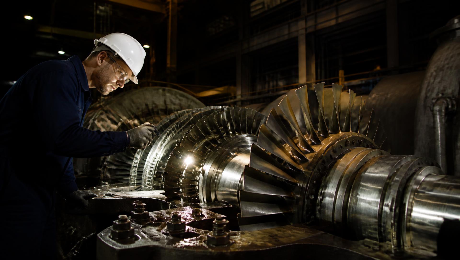
Vibration, bearing distress, oil leakage, seal loss, imbalance, thermal position error, casing distortion and pipe strain can all be present on the same machine train at the same time, and each one will hide behind the others in the trend data. A rebuild that corrects only what was obvious reinstalls the rest. The work of the overhaul is to name every mechanism, measure it, disposition it, and then demonstrate that the reconstructed train has reached the engineered condition required for the next operating campaign.
01
One shaft line, several independent failure mechanisms
A power recovery train couples machines with very different behaviour onto one shaft line. A steam turbine or motor driver supplies or absorbs power, an expander recovers energy from hot process gas, a compressor or process air blower does the work the plant actually depends on, and a special purpose gear may sit between them. Each machine has its own thermal state, its own rotordynamic behaviour and its own failure modes, and each is mechanically connected to the others through couplings, a shared baseplate and connected piping.
That connection creates a transmission path. It does not establish a causal direction. High vibration measured at the compressor bearings can originate in the compressor rotor, in the coupling, in the gear mesh, in the turbine casing position, in the foundation, or in a pipe support that failed two years earlier. The most common mistake on a train of this kind is to correct the machine where the amplitude is highest rather than the machine where the mechanism lives.
Before any decision is taken about scope, the question to answer is not what needs replacing. It is what is actually wrong, how many separate things are wrong, and which of them will still be wrong after the parts are changed.
The overhaul is won before the rotor turns.
02
Reading the pre-overhaul evidence
The condition record built before the train is opened is the only opportunity to characterise the machine in its failed state under real load. Once the coupling bolts come out, that evidence is gone. A disciplined pre-outage data capture is worth more to the rebuild than anything measured in the shop.
The objective is not a vibration report. It is a description of behaviour: what the train does at speed, under load, during transients, when hot, and what it did differently six months ago.
- Spectrum and Waveform
- Synchronous and non-synchronous content, harmonics, subsynchronous activity, gear mesh frequency and sidebands, and rolling element or pad passing content where present.
- Phase
- Relative phase across bearings and across couplings, which distinguishes unbalance from misalignment and from a bent or bowed rotor far more reliably than amplitude.
- Orbit and Shaft Centreline
- Orbit shape and precession direction for rub, oil whirl and preload, and shaft centreline position through startup to show how each journal actually moves as the train heats.
- Run-up and Coastdown
- Bode and polar data through critical speeds, with the field or driver removed where practical, which separates forced response from resonance and from electromagnetic or process forcing.
- Bearing Temperatures
- Metal temperature by pad and by bearing, trended against load, oil supply temperature and ambient, and compared across the train.
- Oil Analysis and Debris
- Particle count, water content, viscosity, spectroscopic wear metals and ferrography, which identify which bearing or gear is shedding material before it is visible.
- Seal and Leak History
- Oil leakage locations and rates, seal gas or seal oil behaviour, drain flows and vent condition, treated as data on internal clearance and shaft position rather than as housekeeping.
- Process and Load Correlation
- Historian records of speed, load, flow, pressure, inlet temperature, surge margin and steam conditions, time synchronised with the vibration record.
- Event History
- Trips, upsets, water carryover, surge events, overspeed events, prior balancing, prior alignment work and prior repairs, with dates that can be aligned against the trend.
03
Separating the findings before assigning the scope
Every credible mechanism is carried forward until a measurement excludes it. Several are usually present together, and a rebuild scope written from the first plausible explanation tends to reinstall the rest.
Each of the conditions below has a signature and a confirming measurement. The discipline is to name both, in writing, before the scope is priced.
- Unbalance: predominantly synchronous, stable phase, amplitude rising with speed, confirmed by balance response and residual unbalance measurement rather than by spectrum alone.
- Misalignment: axial and radial synchronous content with characteristic phase relationships across the coupling, confirmed by alignment measurement and by how the condition changes between cold and hot.
- Mechanical looseness: harmonic families, directional amplitude, unstable phase, confirmed by soft foot checks, fastener condition and structural response testing.
- Rub: subsynchronous or harmonic content, distorted orbit, reverse precession, confirmed at disassembly by contact evidence on seals, glands or labyrinths.
- Journal bearing distress: changed clearance behaviour, shifted shaft centreline, elevated metal temperature, confirmed by dimensional inspection and babbitt condition.
- Oil whirl or whip: subsynchronous activity near a fraction of running speed or locked to a critical, confirmed by bearing geometry, clearance, preload and oil supply condition.
- Structural resonance: response amplified in one direction and at one location, confirmed by bump testing, modal analysis or operating deflection shape, not by inference from the spectrum.
- Casing or diaphragm distortion: clearance asymmetry and thermal sensitivity, confirmed by bore and internal dimensional survey with the casing supported as installed.
- Pipe strain: alignment that changes when flanges are broken, confirmed by measured nozzle movement during disconnection.
- Gear condition: mesh frequency, harmonics and sidebands with load correlation, confirmed by contact pattern, backlash and tooth condition.
04
Foundation, baseplate, grout and soft foot
A correctly rebuilt rotor set into a compromised support structure will fail again, and the failure will be attributed to the rebuild. Structural condition is assessed before geometry work begins, because everything measured afterwards depends on it.
The assessment covers concrete condition and cracking, grout bond and voids under the baseplate, anchor bolt condition and tension, hold down bolt condition, pedestal integrity, evidence of fretting or movement at machined mounting surfaces, settlement history and structural stiffness in the vibration directions of interest.
Soft foot is measured and corrected before alignment, not during it. A machine bolted down onto an uneven support is distorted at the casing, which changes internal clearances, bearing loading and the alignment condition itself. Shim packs are counted, measured and recorded, and corrosion or excess shim layers are treated as findings rather than as a convenience to be reassembled.
05
Reconstructing the train geometry
Rebuilding a train is the controlled reconstruction of geometry. Every machine has to return to a defined position relative to the others, in three axes, with casings level and internals concentric to the rotor they enclose.
The as-found geometry is recorded before anything is disturbed, so that the difference between as-found and as-left becomes evidence rather than narrative. Shaft centreline elevation, axial position, casing level, bore concentricity, shaft and coupling runout, bearing housing position and stationary component position all form part of that record.
Measurement technology is selected by what is being measured. Laser shaft alignment systems are appropriate for shaft to shaft alignment and for measured thermal movement. A laser tracker or precision optical survey is appropriate for train level geometry, elevations, casing position and foundation reference points across distances where shaft mounted systems cannot reach. Dial indicators, precision levels, micrometers, bore gauges, feeler gauges and depth gauges remain the correct tools for runout, clearance, bore and fit work, and all of them are calibrated with certificates retained.
06
Thermal growth and the engineered cold target
Cold alignment is not the alignment target. On a hot train, the machines are deliberately positioned away from concentric when cold so that their shaft centrelines converge at normal operating temperature. One machine may be set relatively high, another relatively low, and lateral offsets may be specified as well. The direction and magnitude are machine specific and come from the OEM basis, not from a rule of thumb.
The chain of reasoning is explicit: predicted cold offset, then measured cold alignment against that engineered target, then operating thermal growth, then validated hot behaviour. Any link taken on assumption weakens the whole rebuild.
Thermal growth is not a single number. Vertical growth of casings and bearing pedestals, horizontal movement about the anchor point, axial growth toward and away from fixed feet, differential growth between machines of different materials and temperatures, coupling growth and spacer change, thrust position shift, piping reaction at temperature, foundation temperature and startup heating rate all contribute. A cold error of a fraction of a millimetre at the coupling can translate into substantial bearing and coupling load once the train is hot, and the machine will report it as vibration that appears only at load.
Direct hot alignment on an enclosed, insulated train is rarely straightforward. The honest position is that growth is predicted from the OEM basis and material data, verified against shaft centreline position from the proximity probes as the train heats, corroborated by casing and pedestal temperature mapping and by historian correlation, and measured directly by laser or optical hot checks only where access and safety allow. Where historical machine behaviour contradicts the OEM prediction, the discrepancy is reconciled and documented before the cold target is set, not averaged away.
07
Rotor inspection and reconstruction
The rotor is received, cleaned and inspected to a written incoming inspection plan with as-found dimensions recorded before any material is removed. The temptation on a schedule driven outage is to clean, polish and measure afterwards, which destroys the evidence of what the machine was actually doing.
Dimensional work covers shaft straightness and runout at defined stations, journal diameter, ovality and taper, coupling fits and their interference condition, keyways, threads, thrust collar face runout and squareness, seal and probe target areas, and the condition of blades, impellers, discs, tenons, shrouds and shrink fitted attachments. Erosion, corrosion, fretting at fits, cracking at stress concentrations, rub evidence and deposit accumulation are mapped by location rather than described.
Nondestructive examination is selected by material, geometry and the mechanism suspected: magnetic particle and liquid penetrant for surface indications, ultrasonic for subsurface and bore examination, eddy current for blade and non ferrous applications where appropriate, and borescope examination of internal passages. Where an indication is found in a highly stressed feature, metallurgical evaluation determines mechanism before any repair decision is taken.
Repairs on a special purpose rotor are an engineering disposition, not a shop acceptance. Weld repair, blade replacement, journal restoration and material removal in a fillet all change stress, mass distribution and in some cases rotordynamic behaviour. Each requires a written disposition covering technical basis, procedure qualification, examination after repair and the effect on balance and on the rotordynamic model.
08
Rotor balancing, and what balancing cannot fix
Balancing is a separate discipline from vibration troubleshooting and should not be treated as its remedy. Components are balanced individually where the assembly method requires it, the assembled rotor is balanced as a unit, and residual unbalance is measured and certified against an acceptance criterion appropriate to the machine class, with ISO 21940 balance quality grades and the OEM requirement both applied and the stricter one governing.
The decisions that matter are the number and location of correction planes, whether corrections are made by material removal or by added weight, whether low speed balancing is sufficient or a high speed balance in a vacuum facility is justified by flexible rotor behaviour or by OEM requirement, whether an overspeed run is required, and how the coupling hub is treated during balancing so that the as-assembled condition matches the balanced condition.
Any component fitted after balancing, or any disassembly and reassembly of a balanced rotor, invalidates part of the result unless the assembly is indexed and controlled. That detail is regularly missed and regularly explains a rebuilt machine that runs rough from the first start.
Balancing corrects mass eccentricity. It does not correct misalignment, looseness, structural resonance, rubbing, bearing defects, casing distortion, pipe strain or thermal position error. A train balanced to correct a symptom caused by one of those will run acceptably in the shop and poorly in the field.
09
Bearings: geometry before condition
Bearings are where alignment error, unbalance, distortion and lubrication problems are ultimately paid for, and bearing work is where a rebuild is most often judged on appearance rather than on measurement.
For journal bearings, the controlled dimensions are journal diameter, bearing bore, diametral and vertical clearance, shell fit in the housing, and for split precision bore sleeve bearings the crush or interference at the split line. Crush is the small amount by which the two half shells stand proud of the housing joint, so that when the cap is torqued the shell is held firmly in its bore and cannot move or lose heat transfer. It applies to that construction. Tilting pad assemblies are controlled instead by pad thickness, assembled bore, preload and pivot condition, and describing their behaviour in terms of crush is a category error.
For thrust bearings, the controlled items are axial clearance and float, pad thickness uniformity, pivot or leveling link condition, thrust collar face runout, squareness and surface finish, and the active and inactive pad arrangement. Oil feed geometry, orifice sizing, drain capacity and the position and immersion of temperature elements are verified rather than assumed, because a correctly dimensioned bearing that is starved or that reports temperature from the wrong location will still fail.
10
Babbitt repair and the evidence that makes it acceptable
Rebabbitting is a controlled metallurgical process, and the finished part is accepted on evidence rather than on appearance. A typical sequence removes the old babbitt, inspects and examines the backing shell, prepares and cleans the bonding surface, tins the shell, casts or centrifugally applies the new babbitt, rough machines, finish machines to the engineered bore, and then verifies the result.
Acceptance rests on four things demonstrated independently: bond integrity across the full backing surface, dimensional conformance of the bore and the clearance it produces, surface condition and finish, and the absence of casting defects such as porosity, inclusions or shrinkage at the bond line.
Bond integrity is verified by ultrasonic bond inspection, with liquid penetrant at accessible bond edges where the geometry permits it. Dimensional verification is by calibrated bore gauge and micrometer at defined stations, surface finish is measured rather than judged by eye, hardness is checked where the babbitt alloy and the procedure call for it, and installed temperature elements are verified for position, immersion, continuity and calibration before the bearing goes back in.
A bearing is not acceptable because the babbitt is new. It is acceptable when geometry, clearance, surface condition and bond integrity have been demonstrated and recorded.
11
The expander
A hot gas or power recovery expander lives in the harshest environment on the train. It is exposed to process temperature, to particulate carryover and to deposits, and its clearances are set against a casing that moves substantially between cold and operating condition.
Inspection covers rotor blades and their attachments, tenons and shrouds, disc condition, the nozzle or stator assembly, erosion and particle impact damage, high temperature corrosion and oxidation, deposit accumulation and its effect on balance, seal and tip clearances, casing distortion and thermal deformation, and internal concentricity of the rotor within the stationary geometry.
A perfectly rebuilt rotor installed into a distorted casing will not deliver reliability. If the casing halves no longer close to a round bore, if the horizontal joint has been dressed repeatedly, or if thermal cycling has permanently deformed the hot section, clearances will be asymmetric, rub risk is concentrated at the tight positions, and vibration will be thermally sensitive from the first hot run. Internal geometry is therefore surveyed with the casing supported as it will be installed, not lying unsupported on the shop floor.
12
The compressor or process blower
Where the compressor drives a process that cannot run without it, compressor reliability is plant reliability, and the overhaul acceptance criteria should reflect that rather than defaulting to generic mechanical limits.
The scope covers rotor and impeller or blade condition, fouling and deposit removal with attention to the balance consequence, erosion and corrosion, labyrinth and shaft seal condition and clearance, stationary diaphragm and diffuser components, rotor to stator concentricity, casing condition and joint integrity, inlet guide vane mechanisms where fitted, and bearing condition assessed against the aerodynamic loading the machine actually sees.
Aerodynamic condition is part of the rebuild, not a separate performance matter. Clearance restoration changes efficiency and changes the surge line. The anti surge system, its control valve stroke and response, and the instrumentation it depends on are verified in the same outage, and a post overhaul performance baseline is taken so that later degradation can be measured against a known starting point rather than against the design curve.
13
The steam turbine or driver
Turbine work covers rotor condition and blade integrity, diaphragms and nozzle blocks, gland and interstage seals, casing condition and joint integrity, steam path deposits and their effect on stage pressures and on balance, valve condition and stroke, and the trip and overspeed protection system.
The thermal behaviour items are specific to this machine and belong in the record: differential expansion range, eccentricity at turning gear, thermal bow behaviour on shutdown and restart, rub evidence at glands, and the casing support and keyway condition that allows the machine to expand as designed. A turbine that cannot slide on its supports will transfer that restraint into the coupling and into the next machine.
API 612 applies to special purpose steam turbines and sets the framework for the machine and its accessories. Where the OEM requirement is stricter or more specific, the OEM requirement governs, and the distinction between the two is stated in the disposition rather than blurred.
14
The gear unit, where fitted
A special purpose gear is its own subsystem and is treated as one. Inspection covers the high speed and low speed shafts, pinion and bull gear tooth condition, contact pattern under a controlled check, backlash, axial position and end float, bearing clearances, gear and shaft runout, tooth wear, pitting, spalling and scuffing, casing condition and bore alignment, thermal growth of the casing and pedestals, and the lubrication supply to each mesh and bearing.
Diagnostically, the gear is read through gear mesh frequency, its harmonics, and the sideband families around them, together with shaft order content, phase and load correlation. Sideband growth with load is the signal that most often distinguishes a genuine mesh problem from a shaft or coupling problem measured at the gearbox. Oil debris analysis and magnetic plug inspection complete the picture.
API 613 applies to special purpose gear units in this service and governs rating, tooth geometry, lateral and torsional behaviour and testing. Where the train includes a gear, torsional interaction between machines becomes a real consideration rather than a theoretical one, and the torsional model is checked against the as-rebuilt configuration.
15
Couplings
Couplings are a frequent source of post rebuild trouble because they are the one component whose correct condition depends on two machines at once.
The controlled items are coupling type and its tolerance for the misalignment actually present, hub to shaft fit and the interference or hydraulic mounting method used, recorded advance or draw up, spacer length, installed axial gap, prestretch or compression where the design uses it, bolt condition, bolt torque or measured tension, assembly indexing, coupling balance, hub and assembly runout after mounting, diaphragm or disc pack condition, and lubrication where a lubricated coupling type is used.
Axial position is where the money is. A spacer or gap set to a cold dimension without accounting for the axial growth of both machines will drive the flexible element toward one end of its travel at temperature. On a diaphragm or disc coupling that produces axial reaction force straight into a thrust bearing; on a gear coupling it can cause lock up and transfer a bending moment into both shafts. The machine reports it as thrust temperature, axial position drift or load dependent vibration, and nothing about the vibration data points at the coupling.
API 671 applies to special purpose couplings and covers balance, marking, assembly and documentation requirements that should be present in the turnover package.
16
Lubrication and seal oil systems
A mechanically perfect rebuild can be destroyed in its first weeks by dirty oil. Every bearing surface restored in the shop is exposed to whatever is left in the reservoir, the coolers and the piping.
The system work covers reservoir inspection and cleaning, full piping flush with temporary screens at the bearing headers, filter condition and differential pressure, cooler cleaning and leak testing, main and auxiliary pump condition and automatic changeover proof, accumulator precharge, rundown or emergency oil capability demonstrated rather than assumed, and verification of supply pressure, temperature and flow at each bearing.
Acceptance is by measurement: particle count to a defined cleanliness target, water content, viscosity confirmation, and analysis of flush screen debris. A baseline oil sample is taken after commissioning so that wear metals, spectroscopy and ferrography during the campaign are trended against the as-left condition of this rebuild rather than against a generic limit.
API 614 applies to lubrication, shaft sealing and control oil systems for special purpose machinery, and sets the framework for redundancy, instrumentation and cleanliness expectations.
17
Machinery protection and monitoring
The protection system is the only thing standing between a developing fault and a destroyed rotor, and it is routinely returned to service without proof.
Before startup, the installed hardware is verified item by item: X and Y shaft proximity probes at each bearing with correct orientation and mounting, phase reference probe and target, axial position probes, eccentricity probes, differential expansion where fitted, casing accelerometers, bearing metal temperature elements, speed sensing, overspeed protection, lube oil pressure and temperature switches and transmitters, seal system pressures and the process variables used for interlocks.
Verification is physical and documented: probe gap voltage set and recorded, probe and extension cable system calibration against the actual shaft material, mechanical and electrical run-out measured at each probe target area and compensated in the baseline, channel to channel verification through the monitor to the control system, alarm and trip setpoints confirmed against the engineered values, voting logic proof tested, trip and overspeed functions proved by actual test rather than by simulation alone where the machine design permits, and event recording and data capture confirmed to be running before the first roll.
API 670 defines the machinery protection requirements and the probe, monitoring and testing conventions that make this evidence comparable across outages.
18
Rotordynamic and structural verification
If bearing geometry, seal clearance, coupling mass or rotor mass distribution changed during the rebuild, the dynamic behaviour of the train changed with it. Reusing a model built for the original configuration is not verification.
Lateral analysis confirms critical speed locations, separation margin from operating speed and unbalance response at the probe planes, using the as-rebuilt bearing and seal data. Stability analysis is warranted where clearances, seal designs or bearing types changed, or where subsynchronous activity was observed before the outage. Torsional analysis applies where a gear, a variable speed drive or a motor driver is part of the train, and it is checked against the as-rebuilt inertias and coupling stiffness rather than the original submittal.
Structural work is hypothesis driven. Bump testing, modal analysis and operating deflection shape are used when a resonance is suspected in a pedestal, a baseplate or attached structure. Finite element analysis in ANSYS Mechanical is appropriate where a structural or thermal hypothesis needs quantification. Computational fluid dynamics is not a routine overhaul deliverable, and presenting it as one is a credibility problem. It is justified where a specific question requires it: expander hot gas path flow and temperature distribution, compressor aerodynamic recovery after clearance restoration, or inlet and nozzle flow distribution suspected of driving excitation or uneven loading.
API 684 provides the rotordynamic tutorial and evaluation framework that these analyses are written against, and it is the reference that makes the results reviewable by someone outside the analysis team.
19
Pipe strain
A machine can be aligned perfectly and then be pulled out of alignment the moment the piping is bolted up. On a train with hot process gas, steam and large suction and discharge lines, connected piping is one of the largest single sources of repeat misalignment and casing distortion.
Pipe strain is measured, not discussed. Indicators are set at the machine feet and at the shaft, and nozzle movement is recorded as each flange is broken and again as it is drawn up. Movement beyond the accepted threshold is a finding that is resolved by correcting the piping, not absorbed by moving the machine. Flange parallelism and offset are measured before bolts are pulled together, and spring hangers and supports are checked for correct setting, travel and locking pins removed.
Where a piping system is a repeat offender, it is analysed rather than adjusted. CAESAR II is the recognised tool for evaluating nozzle loads against the allowable limits in the applicable machinery standard, for assessing cold spring and thermal expansion behaviour, and for testing whether the support arrangement is capable of protecting the machine at operating temperature. Piping should be cleared before final alignment acceptance, not investigated after the train vibrates.
20
Torque and fastener control
Specified torque and achieved bolt preload are not the same thing. Torque is an input, modified by thread condition, lubrication, surface finish and friction, and on critical joints the scatter between the two can be very large.
Critical joints are made up with calibrated tools and a controlled sequence: calibrated torque wrenches with current certificates, hydraulic torque systems where the joint size requires them, and hydraulic tensioners where simultaneous preload across a bolt circle matters. Sequence, pass pattern, lubricant and final values are specified in the procedure and recorded on completion.
Ultrasonic bolt elongation measurement is genuinely useful on a small number of joints where preload is critical and cannot be inferred, such as certain coupling hubs, thrust or large casing joints, and anchor bolts on a machine with a movement history. It is not a general regime for every fastener on the train, and proposing it as one signals inexperience rather than rigour. Where it is used, the as-installed elongation is recorded per bolt and retained.
21
Dimensional QA and QC
Every critical dimension on the rebuild carries the same five part structure: the requirement and its source, the measurement method and instrument, the acceptance criterion, the qualified person who measured it, and the record.
The dimensions that receive this treatment include shaft and coupling runout, journal and bearing clearance, shell fit and crush, thrust clearance and float, seal and labyrinth clearance, internal rotor to stator clearance at each stage or seal, gear backlash and end float, coupling spacing and axial position, casing bore concentricity, casing level, shaft centreline elevation and axial position, and cold alignment against the engineered target.
Assembled and accepted are different states. A component that is installed has been assembled. A component that has been measured against a written criterion by a qualified person, with the result recorded and approved, has been accepted. Only the second state carries forward into the turnover package, and only the second state is defensible when the machine is examined again after a future failure.
22
Hold point governance
The rebuild is won at the hold points, not at startup. Once the casing is closed, the coupling is made up and the insulation is back on, most of the evidence is unrecoverable and the cost of being wrong multiplies.
Every critical activity runs through the same chain: approved procedure, defined acceptance criterion, qualified person, inspection point, measurement, record, approval. Witness points allow work to continue if the witness is not present; hold points do not. That distinction is agreed in writing before the outage, with the OEM, owner and third party roles named.
- Incoming rotor inspection and as-found dimensions recorded before cleaning or repair.
- Rotor NDE results reviewed and any repair dispositioned in writing before work begins.
- Rotor balance certificate issued and residual unbalance accepted against the criterion.
- Babbitt bond verified by ultrasonic examination before machining to final bore.
- Bearing clearance, crush or preload, and thrust float measured and recorded at assembly.
- Gear contact pattern and backlash measured and accepted before casing closure.
- Internal clearances independently checked and witnessed before the casing is closed.
- Coupling hub mounting, advance, spacer gap and bolt preload recorded.
- Pipe strain measured at flange break and at make up, and cleared before alignment acceptance.
- Cold alignment compared against the engineered thermal offset target and approved.
- Oil flush accepted against the cleanliness criterion, with screen debris documented.
- Probe gaps, run-out compensation, calibration and trip settings verified and recorded.
23
Responsible Engineer review
Before release, conclusions are independently challenged by a Responsible Engineer outside the primary discipline, to test assumptions, methodology, evidence and engineering judgment.
The same principle applies to overhaul acceptance. The engineer who set the thermal offsets should not be the only engineer who approves them, and the team that performed the rebuild should not be the sole authority on whether it meets the criteria. On a critical train, an independent review of the alignment basis, the rotordynamic verification, the bearing acceptance data and the protection system proof is inexpensive relative to a second outage.
24
Commissioning as the final engineering proof
Commissioning is not a formality at the end of the schedule. It is the only stage at which the reconstructed machine can be observed behaving as a system, and it is where the engineered assumptions about thermal growth and dynamics are tested against reality.
A controlled sequence proves the lube and seal oil system first, then the protection and trip system, then turning or barring gear operation and rotor movement, then slow roll with run-out confirmed, then a controlled startup with critical speed passage observed on Bode and orbit data rather than on overall amplitude alone.
From there, loading proceeds in steps with vibration, phase, orbit, shaft centreline position, bearing metal temperatures, axial position, differential expansion, seal behaviour and oil condition observed at each hold, allowing time for thermal stabilisation before the next step. Shaft centreline movement through the heat soak is the practical measurement of whether the thermal growth assumptions were right. A coastdown is recorded at the end of the run, and a post run inspection is performed where the machine class or the findings justify it.
The deliverable is a comparison, not a certificate. The pre-overhaul baseline and the post overhaul baseline are placed side by side so that improvement is demonstrated rather than assumed, and so that the next engineer has a known good condition to trend against.
25
The rebuild once acceptance package
The output of the overhaul should be a machine technical passport: a single controlled package that tells the next engineer what this train is, what condition it was left in, and what evidence supports that statement.
- Mechanical
- As-found and as-left geometry, clearances, fits, runouts, bearing data, rotor condition and repair dispositions, torque and preload records.
- Dynamic
- Balance certificates and residual unbalance, critical speed and separation margin, unbalance response, and the post overhaul vibration, phase and orbit baseline.
- Alignment
- Engineered cold target and its basis, as-left cold alignment, thermal growth assumptions, pipe strain measurements and hot verification data.
- Lubrication
- Flush acceptance and cleanliness results, system pressures and temperatures, rundown proof and the baseline oil analysis.
- Instrumentation
- Probe calibration and gap settings, run-out compensation, alarm and trip values, protection system proof test records.
- Reliability
- Updated FMECA and criticality, inspection and monitoring intervals, thresholds, shutdown criteria and the spares position.
- Records
- Incoming inspection, NDE, welding and heat treatment records, calibration certificates, nonconformances and their dispositions, commissioning data and final as-left dimensions.
26
Engineering records and the reliability strategy that follows
An overhaul is the one moment when a complete, coherent engineering baseline for the train can be captured. Most of the cost of the next investigation is spent reconstructing information that existed during this outage and was never assembled.
The turnover package is indexed and held as a controlled record rather than distributed as loose reports. BPG Engineering Records Intelligence structures the overhaul record so it is searchable and comparable at the level of individual measurements, and TerraTolga Vault Compare supports comparison of as-found against as-left, and of this outage against the previous one, so that drift in clearances, alignment and balance condition is visible across campaigns rather than rediscovered.
The rebuild then resets the reliability strategy rather than restarting the previous one. FMECA and criticality are updated against what was actually found, condition monitoring thresholds are reset to the new baseline, inspection and oil analysis intervals are set against the mechanisms that were live on this machine, and shutdown criteria are written in terms the control room can act on. The BPG and TerraTolga FMECA Engine and Criticality tooling carry that forward into the maintenance plan. The objective is a sequence that ends before the next outage does: rebuild, establish baseline, monitor degradation, intervene before failure.
27
Spares: which single item keeps the plant down for six months
The spares question on a critical train is not how much inventory to hold. It is which single unavailable component converts a short repair into an extended business interruption, and whether that component is on site.
Candidates are assessed by lead time, criticality and failure likelihood together: a spare rotor for the machine with the longest manufacturing lead time, complete journal and thrust bearing sets, thrust pads, seals and labyrinths, coupling hardware and spare flexible elements, gear components where the gear is single source, vibration and phase reference probes with extension cables, speed sensors, control and servo components for the governing and trip systems, expander hot section hardware, and specialty fasteners that are not commercially available.
Each is categorised as a capital spare, an insurance spare, a turnaround spare or a consumable, and the categorisation is linked directly to the business interruption exposure it protects against. A spare rotor is an insurance decision with a financial answer, not a maintenance preference.
28
What "recently overhauled" actually means
In a transaction, the phrase carries weight it has not earned. A weak diligence process reads recent overhaul completed and prices the risk as retired. A completed overhaul with weak records can equally be an outage already scheduled by physics and not yet by the plant.
The diligence test is not whether the work was done. It is whether the work was verified, and whether the verification survives independent review.
- Was the rotor completely inspected, with as-found dimensions and NDE results retained?
- Were repairs engineered and dispositioned in writing, or accepted at the shop floor?
- Was the bearing babbitt bond verified by examination, or accepted on appearance?
- Were cold alignment offsets based on an engineered thermal growth basis, or set to zero?
- Was hot behaviour validated, and does shaft centreline data exist to show it?
- Was the rotor balanced to a stated criterion, with the certificate retained?
- Was pipe strain measured at flange break and make up?
- Were coupling axial position, spacer gap and bolt preload recorded?
- Was the lubrication system flushed to a cleanliness target, with results documented?
- Were vibration and phase probes calibrated, with run-out compensated in the baseline?
- Were the trip, overspeed and voting logic functions proof tested?
- Were internal clearances independently verified before casing closure?
- Was the machine commissioned under controlled load steps with thermal stabilisation?
- Does a post overhaul vibration and performance baseline exist to trend against?
- Are the critical long lead spares identified and held?
29
Investment committee translation
Each engineering finding on a train of this kind maps to a financial consequence that a committee can price. The translation below is the form in which these findings belong in a diligence report.
- Incorrect thermal alignment
- Repeat bearing and coupling failure risk, with the failure appearing only at load and typically within the first operating campaign.
- Poor bearing rebuild
- Early outage and potential rotor or journal damage, converting a bearing replacement into a rotor repair.
- Inadequate balancing
- Persistent vibration exposure, reduced operating envelope and constrained load following.
- Pipe strain
- Misalignment and casing distortion reintroduced after every alignment, with no lasting correction available in the field.
- Weak oil cleanliness
- Bearing and gear surface damage accumulating from the first hours of operation.
- Missing strategic spare
- Extended business interruption governed by manufacturing lead time rather than by repair duration.
- Poor QA and QC records
- Overhaul quality unquantified, so the completed CAPEX cannot be credited against future risk.
- No post overhaul baseline
- Limited ability to detect deterioration, so the next failure is discovered rather than predicted.
- Distorted casing or incorrect clearances
- Reduced reliability and efficiency, with rub risk concentrated where clearance is tightest.
- Incomplete instrumentation
- A developing failure can progress without alarm, removing the protection the model assumed.
30
Standards backbone
The standards below form the working framework for a train of this type. In each case the current edition applies, and three categories are kept distinct: what the standard requires, what is recommended engineering practice, and what is an OEM specific requirement. Where they conflict, the stricter and more specific requirement governs, and the reason is documented.
- API 686, machinery installation and installation design, including alignment and grouting practice.
- API RP 687, repair of special purpose rotating equipment, including rotor repair and bearing work.
- API 684, rotordynamic tutorial and evaluation, for lateral, torsional, stability and balance response work.
- API 612, special purpose steam turbines.
- API 617, axial and centrifugal compressors and expander compressors, noting that a hot gas power recovery expander may fall partly outside its scope and be governed by OEM requirements.
- API 613, special purpose gear units.
- API 614, lubrication, shaft sealing and control oil systems.
- API 670, machinery protection systems.
- API 671, special purpose couplings.
- ISO 21940 for rotor balance quality and residual unbalance, and ISO 20816 for vibration evaluation on installed machines, with ISO 10816 references retained where legacy plant data uses them.
- ASME Section V and ASNT qualification requirements for NDE method, procedure and personnel.
- ASME Section IX and the applicable construction code for any weld repair procedure and welder qualification.
31
Tools and analysis stack
The tools below are the ones a senior rotating equipment engineer would expect to see named, separated by what they are actually for. Monitoring, diagnostics, rotordynamic modelling and structural modelling are four different activities and are not interchangeable.
- Condition Monitoring
- Bently Nevada System 1 for continuous machinery condition data, alarming and trending across the train.
- Machinery Diagnostics
- Bently Nevada ADRE for high resolution transient capture, run-up and coastdown, Bode, polar, orbit, cascade and order tracked data, with portable FFT, waveform and phase analysers for field work.
- Rotordynamics
- DyRoBeS and XLTRC2 for lateral, torsional, stability and unbalance response analysis against the as-rebuilt configuration.
- Structural and Thermal FEA
- ANSYS Mechanical for modal, harmonic and thermal stress work where a structural hypothesis needs quantification.
- Piping Stress
- CAESAR II for nozzle load evaluation, thermal expansion behaviour and support adequacy.
- Alignment and Geometry
- Prueftechnik, Easy-Laser and Fixturlaser shaft alignment systems, with laser tracker and precision optical survey for train level geometry and elevations.
- Balancing
- Schenck and Hofmann class balancing machines for component and assembled rotor balancing, with field balancing performed through the diagnostic platform.
- Nondestructive Examination
- Ultrasonic and phased array, magnetic particle, liquid penetrant, eddy current where appropriate, and industrial borescope and videoscope examination.
- Bearing QA
- Ultrasonic babbitt bond inspection, calibrated bore and dimensional metrology, and surface finish measurement.
- Oil and Wear Monitoring
- Particle counting, spectroscopic wear metal analysis, ferrography and water content measurement, trended from the commissioning baseline.
- Historian and Operations
- AVEVA PI or equivalent for load, process and temperature correlation with time synchronised machinery data.
- Asset and Maintenance Records
- SAP S/4HANA Asset Management and IBM Maximo for work history, strategy and spares, depending on the plant system of record.
- BPG and TerraTolga
- Engineering Records Intelligence and Vault Compare for the overhaul record and as-found against as-left comparison, and the FMECA Engine and Criticality tooling for the reliability strategy that follows.
32
Assembling the right specialists at the right point
No single engineer covers rotordynamics, metallurgy, NDE, bearings, alignment, lubrication, piping stress, instrumentation, commissioning and records at the depth a critical train deserves. The failure mode on large overhauls is not usually an absence of expertise. It is expertise applied at the wrong moment, to a question that had already been closed by somebody else.
BlackOut Power Group's role is not to replace each specialist. It is to ensure that the right specialist answers the right question at the right point in the rebuild, that the acceptance criteria are set before the work rather than negotiated after it, and that every piece of evidence converges into one controlled technical acceptance process that a lender, an insurer or a future investigator can read.
33
A rebuild is not successful because the machine starts
A train will start in many conditions it should not be operated in. It will run through a shift with the wrong thermal offsets, with a coupling loaded axially, with a bearing that is out of clearance, with oil that is dirty, and with a protection channel that would not have tripped it. All of that is invisible on the day the machine is handed back.
An overhaul is successful when geometry, thermal growth, rotor dynamics, bearings, lubrication, internal clearances, instrumentation and operating behaviour have all been demonstrated to be within the engineered condition required for the next operating campaign, and when the evidence for each of them exists in a form someone else can check.
That evidence is produced at the hold points, in the shop and on the baseplate, long before the first roll. The overhaul is won before the rotor turns.
Related Capability
Continue Reading
- A Pressure-Tight Joint Is Not a Durable Joint: Why Heat Exchangers Keep Leaking Before You Change the Alloy
Pressure Equipment / Owner's Engineering
- From Factory Lot to Live Data Hall: Engineering the Fiber Lifecycle to Prevent Latent Failure
Mission Critical
- Recovery Boiler Tube Failure: When the Failed Tube Is Not the Root Cause
Pressure Systems